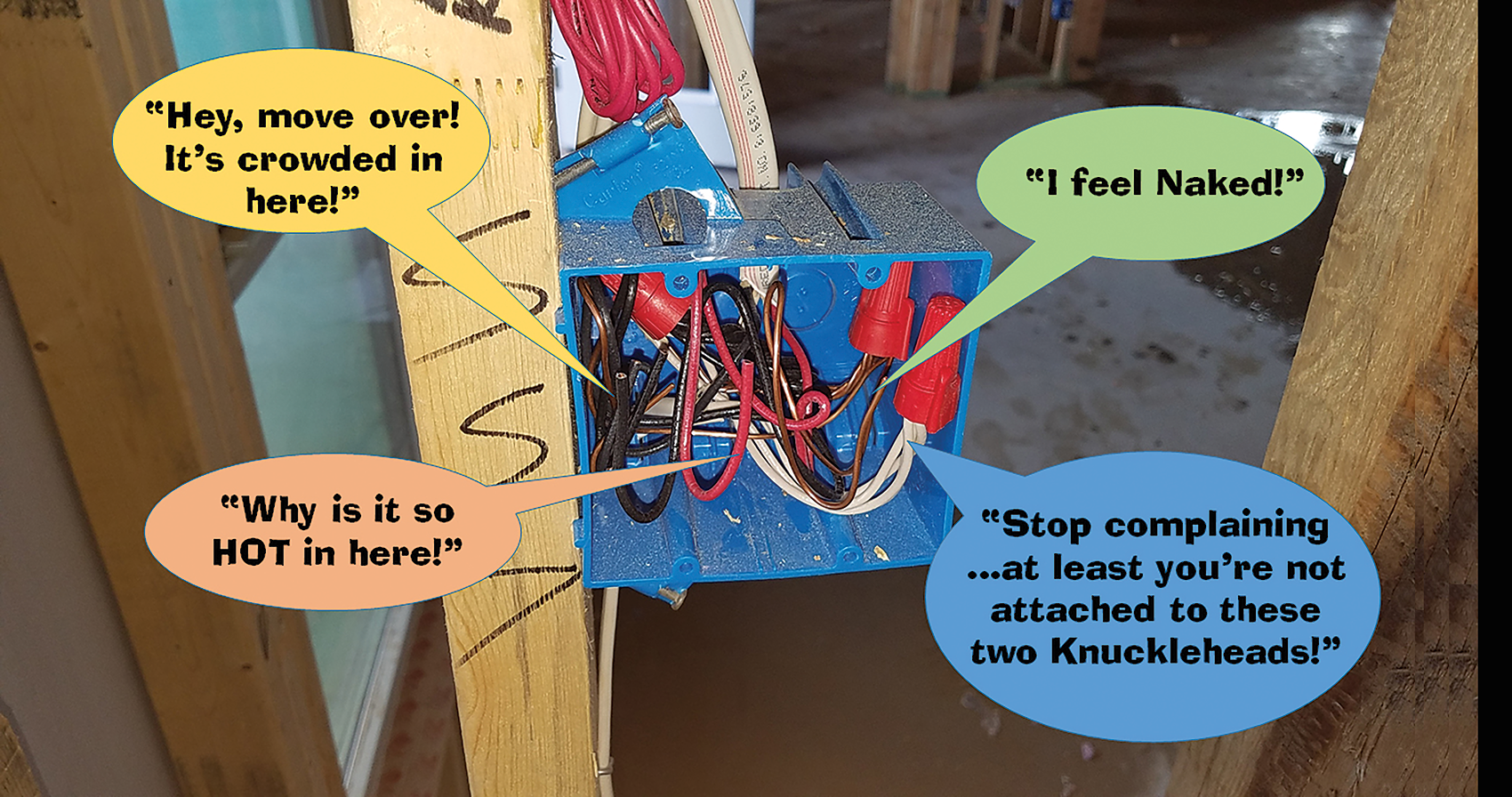
One of the most frequently encountered Code violations, in my experience, would have to be those concerning box fill requirements. More conductors, devices, fittings, etc., are often installed in a box than what that particular box was designed and listed to contain. Unfortunately, these over-crowded boxes are all too common at both residential and commercial applications.
One might say, “OK, what’s the big deal; what’s the harm?” When put to work carrying the load they are intended to carry (such as a lighting load), the enclosed conductors produce heat from current flow associated with these loads. These conductors must have ample free space to allow proper dissipation of heat from the conductor to not cause damage to the surrounding insulation of these said conductors. A crowded elevator heats up fairly quickly because you and the other heat radiators (bodies) don’t have ample room to dissipate the produced body heat. The same principle applies to conductors enclosed in a confined space, such as a switch box.
The National Electrical Code (NEC) contains sufficient rules and requirements that apply to box fill calculation requirements. Most of these requirements can be found in Article 314 (Outlet, Device, Pull, and Junction Boxes; Conduit Bodies; Fittings; and Handhole Enclosures). Let’s look closer at these requirements for box fill calculations.
General Rules for Boxes
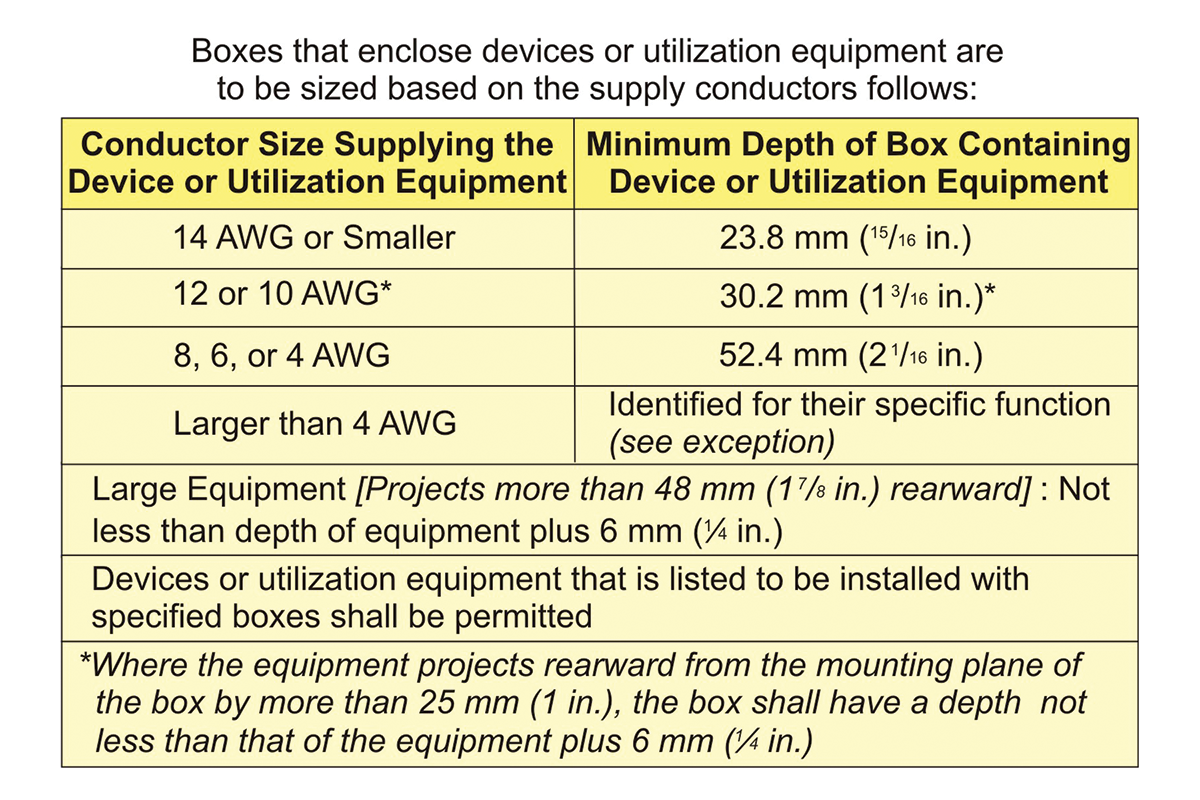
The Code includes general requirements for boxes, such as sizing and support provisions. All boxes (enclosures) must be large enough to provide for sufficient free space for all conductors and devices that will be enclosed within them to prevent overcrowding and possible physical damage when the devices or splices are installed or completed. Outlet boxes that do not contain devices or utilization equipment are permitted to have an internal depth of less than 12.7 mm (½ in.). Boxes that enclose large equipment are required to have a depth that is not less than the depth of the equipment plus 6 mm (¼ in.). Large equipment is defined as devices or utilization equipment that projects more than 48 mm (1 ⅞ in.) rearward from the mounting plane of the box [see NEC 314.24].
Other boxes that enclose devices or utilization equipment are to be sized based on the supply conductors that supply the devices or utilization equipment (see Table 1). In completed installations, each box is required to have a cover, faceplate or luminaire canopy. One reason behind this rule is that if a failure occurs, it is likely to occur at a joint, splice, or termination. This type of failure often starts with a loose connection, and may result in a great deal of heat and be accompanied by arcing. A box or conduit body reduces the likelihood of adjacent combustible materials being ignited by heat or arcing (see NEC 314.25 and 410.22).
Screws used for the purpose of attaching covers, or other equipment, to the box are required to be either machine screws matching the thread gauge or size that is integral to the box, or must be in accordance with the manufacturer’s instructions. This means the use of drywall screws or sheet-metal screws for attaching covers, luminaires, or other equipment to boxes is unacceptable. This crude practice can result in damage to the box and inadequate support of the attached cover, luminaire, or equipment itself [see NEC 314.25, 404.10(B), or 406.5].
Metal boxes, covers, or cover plates are required to be grounded. NEC 250.110 specifically requires that exposed non–current-carrying metal parts of fixed equipment be grounded by connection to the equipment grounding conductor. Specifically, 250.110(5) requires that a metal box or enclosure be grounded if supplied by a metal raceway, metal-clad or metal-sheathed cable, or other wiring method that includes an equipment grounding conductor. The attachment of a metal cover or plate to an effectively grounded enclosure or device usually fulfills this requirement [see NEC 250.110(5), 314.4, or 314.28(C)].
Metal boxes usually have a means for connecting the box to an equipment grounding conductor. Typically, this consists of a 10-32 tapped hole. Some nonmetallic boxes contain an integral means for bonding switches and metal faceplates to the equipment grounding conductor. The bonding means may be a metal strap or band that links the device mounting screw to an equipment grounding terminal [see NEC 314.40(D)].
Box Volume Calculations
Volume of a box is the total volume in cubic millimeters or cubic inches of the assembled sections. Where used, the space provided by plaster rings, domed covers and extension rings that are marked with their volume in cubic inches is included. If the extension ring is made of metal and corresponds to a size listed in NEC Table 314.16(A), the appropriate volume for that size box is used as the volume of the extension ring. Total volume is the volume of the box plus the volume of any attached plaster rings, extension rings, or domed cover.
This total volume (space) determines the number and size of conductors and wiring devices permitted to be contained in the box. Conductors, internal clamps, support fittings, barriers, and devices such as switches and receptacles take up space within the box. The Code assigns to each conductor, clamp, support fitting, barrier, device, and equipment grounding conductor an associated volume allowance. This volume allowance is listed in cubic inches or cubic centimeters. NEC Table 314.16(B) lists the volume allowance as a function of conductor size. The volume allowance for each conductor, clamp, support fitting, barrier, device, and equipment grounding conductor is added together. The box must have a volume that equals or exceeds the total volume required for the contained items.
Where a box is provided with one or more securely installed barriers, the volume is to be allocated to each of the resulting spaces. Each barrier, if not marked with its volume, is to be considered to take up 8.2 cm3 (1∕2 in3) if metal, and 16.4 cm3 (1.0 in3) if nonmetallic. These volume considerations for barriers were added to the 2017 NEC [see NEC 314.16(A)]. Each space within a box installed with a barrier must be calculated as separate boxes on each side of the barrier [see NEC 314.16(B)].
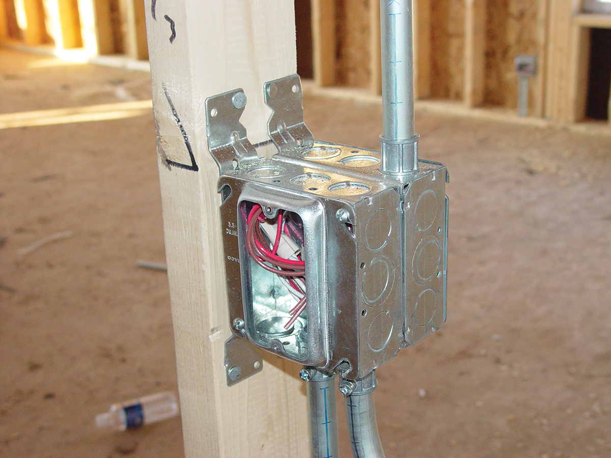
Sometimes, more conductors end up in boxes than were originally intended. For example, the conduit may be of sufficient size for a new circuit; however, the pull or outlet box may not have sufficient volume. Where practicable, an extension ring that is the same shape as the box can be installed; this will add the required additional space so the original box does not have to be replaced. Sometimes it is necessary to replace the original box with a deeper metallic or nonmetallic box to achieve the required volume of space [see NEC 314.16(A)].
Standard Metal Boxes
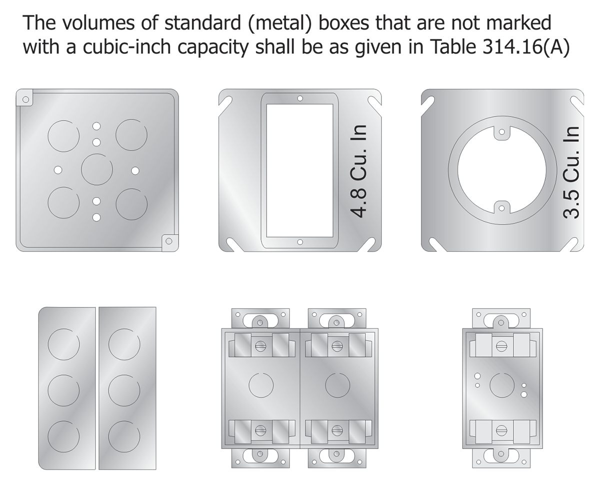
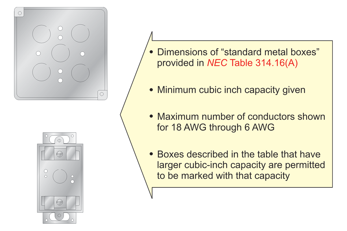
The Code covers the maximum number of conductors permitted within a standard metal box. These boxes may have their cubic millimeter (cubic inch) capacity marked on the box where the capacity is larger than given in the volume allowance table, but that is not an NEC requirement.
Table 314.16(A) in the NEC provide box dimension and trade size in inches for standard metal boxes. The minimum cubic millimeter (cubic inch) capacity for each standard size metal box is given along with the maximum number of conductors of sizes 18 AWG through 6 AWG permitted in the box. As shown in the table, the number of conductors permitted applies only where all conductors are the same size. Where a box contains conductors of different sizes, the required volume of the box must be calculated.
A calculation is also required if the box contains devices, clamps, barriers, or support fittings. No volume allowances are required for small fittings such as locknuts and bushings [see NEC 314.16(B)].
Other Boxes (Nonmetallic Boxes)
Metal boxes may be manufactured in sizes other than those listed in NEC Table 314.16(A). This type of box is called a non-standard box. Nonmetallic boxes made in custom sizes are called non-standard as well, if their dimensions different from those in NEC Table 314.16(A). All non-standard boxes must have their cubic millimeter (cubic inch) capacity durably and legibly marked by the manufacturer on the inside of the box. Additional markings on nonmetallic boxes may include the type of fire-resistive wall, floor, or ceiling assembly for which the box is suitable. A box listed for the support of a luminaire or lampholder in a ceiling shall be designed for the purpose and is required to support a luminaire weighing a minimum of 23 kg (50 lb). Boxes used at luminaire or lampholder outlets on a vertical surface or in a wall are required to be designed for the purpose. They are also required to be marked by the manufacturer on the interior of the box itself to indicate the maximum weight of the luminaire that is permitted to be supported by that box on a vertical surface [if other than 23 kg (50 lb)]. Vertical surface or wall-mounted device boxes are permitted to support luminaires that weigh not more than 3 kg (6 lb). These device boxes may not be marked as being suitable for luminaire support since that is not their primary purpose. The luminaire or its supporting yoke must be secured to the box with at least two 6-32 screws [see NEC 314.27(A)].
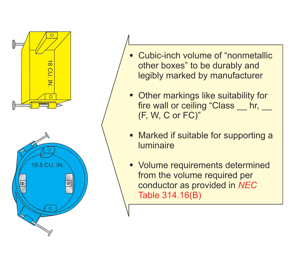
Requirements for determining the maximum number of conductors permitted in non-standard or nonmetallic boxes are given in NEC 314.16(B). The individual volume of each conductor, clamp, and fitting is provided in this volume allowance table. The minimum volume of the box is the total of the individual volumes required for each conductor, device, barrier, or fitting.
A typical nonmetallic, single-gang device box typically used for new construction does not have internal clamps. The openings on a single-gang nonmetallic box are considered knockouts. As a result, no volume allowance for clamps is required on a single-gang nonmetallic box if the installation complies with 314.17(C), Exception. Multiple-gang device nonmetallic boxes and round or octagonal boxes have internal clamps. These clamps may be field-installed or incorporated into the box by the manufacturer. A single volume allowance is made for one or more internal clamps that are present in the box. The volume allowance for clamps that are an integral part of the box construction is included in the marked volume of the box. This requirement will be discussed in further detail later in this article.
Box Fill Calculations
The Code provides the method for determining the minimum cubic millimeter (cubic inch) volume required in non-standard or nonmetallic boxes. This same method is also used to determine the minimum volume of standard metal boxes that have more than one size of conductors or any devices installed in them. This method requires the addition of all the allowances required for various items, and this sum then becomes the minimum volume required for the box. At that point, the size of a standard (metal) box or nonmetallic box with a cubic inch volume that equals or exceeds the volume required can be determined.
As stated previously, no allowance is required for small fittings in boxes such as for locknuts, bushings and parts of cable connectors that are inside single-gang nonmetallic boxes. Cubic millimeter (cubic inch) volume for each item that must be considered is given in NEC Table 314.16(B). This table gives the cubic millimeter (cubic inch) volume allowance required for conductors from 18 AWG through 6 AWG.
Conductor Fill
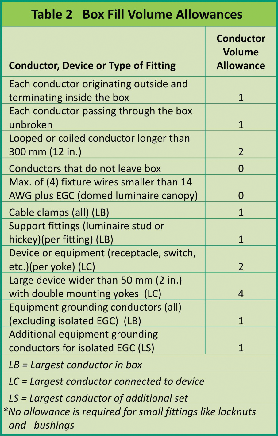
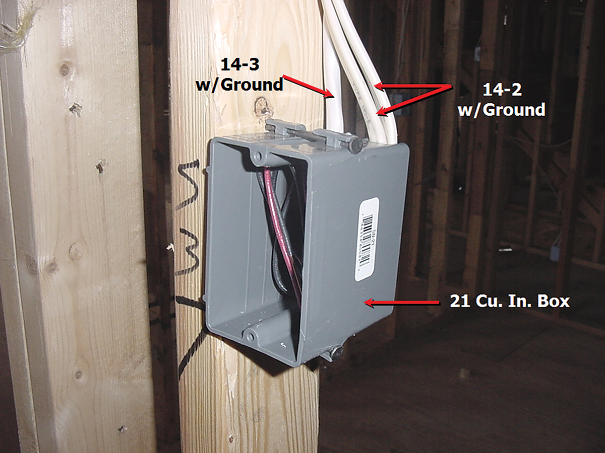
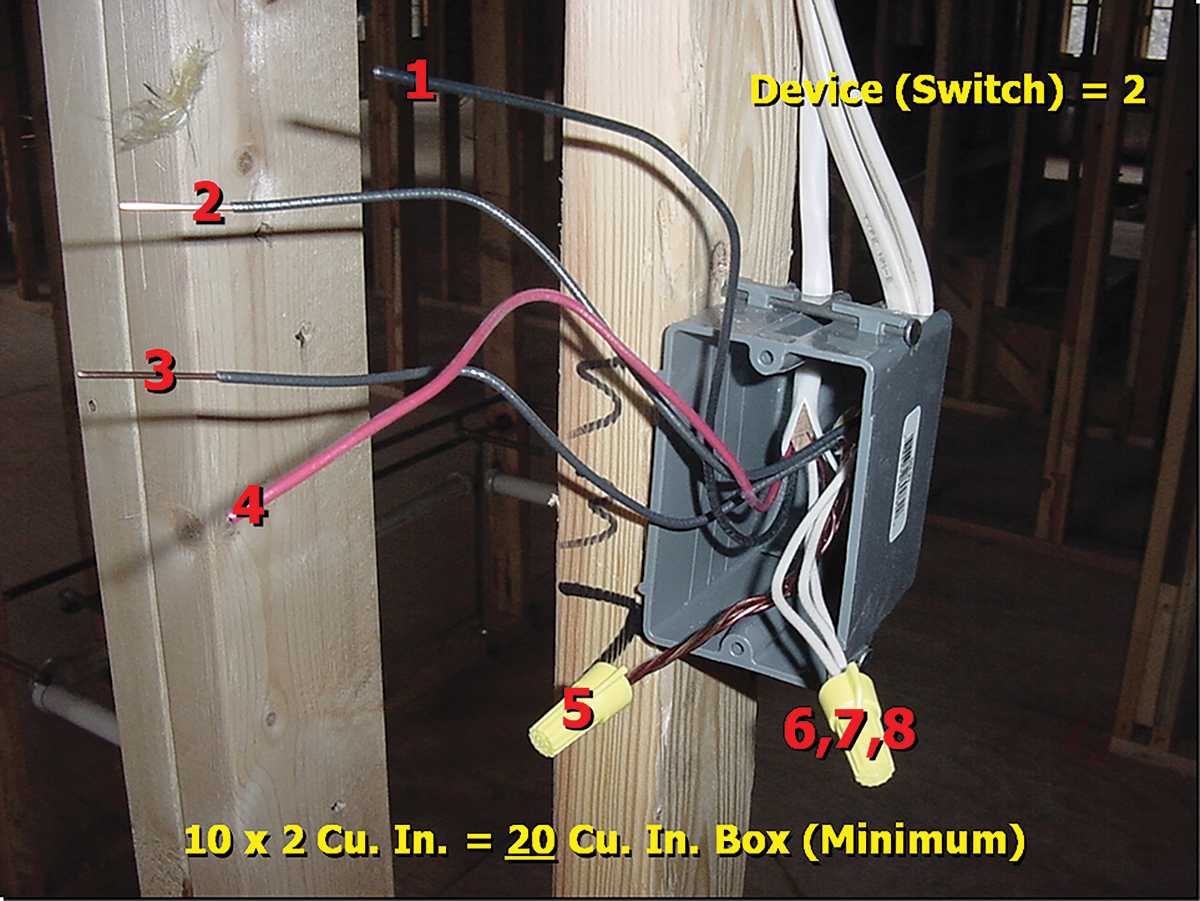
The Code requires each conductor that originates outside the box and terminates or is spliced within the box to be counted once. Each conductor that passes through the box without splice or termination is also required to be counted once. A looped, unbroken conductor 300 mm (12 in.) or longer is counted as two conductors. A conductor which originates in, and of which no part leaves the box, is not required to be counted. These are often jumpers or “pigtails” to wiring devices.
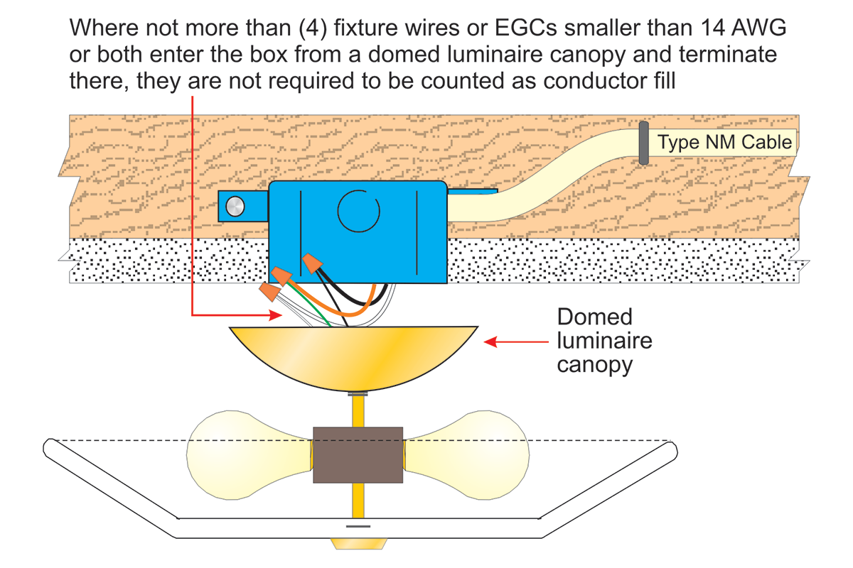
An exception to this rule applies to the conductors that are part of the luminaire wiring. It permits equipment grounding conductor(s) or not more than four fixture wires smaller than 14 AWG, or both, to be omitted from the fill calculations. The conductors must enter a box from a domed luminaire or similar canopy, and are required to terminate within the outlet box.
Clamp Fill
The Code provides information on the volume required for clamp fill. Where one or more internal cable clamps, whether factory or field-supplied, are present in the box, a single volume allowance in accordance with NEC Table 314.16(B) is required to be made based on the largest conductor present in the box. This section requires a single volume allowance for all the clamps that are internal to the box, regardless of the number of clamps. Volume allowance is required for nonmetallic boxes (other than single-gang nonmetallic boxes) with integral cable clamps. Before the total box volume can be determined on nonmetallic boxes (other than single-gang boxes), the manufacturer is required to remove the internal clamping mechanism; then total box volume is determined by a nationally recognized testing laboratory (NRTL). Single-gang boxes are determined to have knockouts rather than cable clamps, so no deduction is required for cable clamps for single-gang nonmetallic boxes when securing nonmetallic-sheathed cable within 200 mm (8 in.) of the box as allowed by NEC 314.17(C) Exception. No allowance is required to be made for a cable connector with its clamping mechanism outside the box. A clamp assembly listed and marked for use with specific nonmetallic boxes that incorporates a cable termination for the cable conductors have been introduced to the electrical industry in recent years. Conductors that originate within the clamp assembly shall be included in conductor fill calculations as though they entered from outside the box.
Support Fittings Fill
Where one or more fixture studs or hickeys are present in the box, a single volume allowance is required to be made for each type of fitting in the box.
Where both a fixture stud and a hickey are present in the box, two volume allowances must be made. One volume allowance is made for the fixture stud; the other, for the hickey. Each volume allowance is based on the largest conductor present in the box [see NEC 314.16(B)(3)].
For our younger generation of readers, a fixture stud is a fitting that mounts to the top of the box, usually inserts through the knockout of a metal box, and is threaded to accommodate the fixture stem. A hickey is a fitting that can be described as a coupling that has threads the same size as the fixture stem and has an oval-shaped hole on one or more sides for the fixture wires to exit inside the box. The hickey is usually threaded onto the fixture stud with the fixture stem threaded into it. These fittings, while used in many older, existing installations, have fallen out of popular use. Nowadays, a luminaire strap or hanger strap is secured to the box with two 8-32 screws, and the luminaire is mounted to the strap.
Device or Equipment Fill
Minimum requirements for device or equipment fill are also provided in the Code. A double volume allowance is required for each yoke or strap containing one or more devices or equipment. Table 314.16(B) gives the volume allowance. This volume allowance is based on the largest conductor connected to a device(s) or equipment supported by that yoke or strap. This requirement applies to devices such as switches, timers, dimmers, and receptacles. The word equipment is intended to include items like pilot lights.

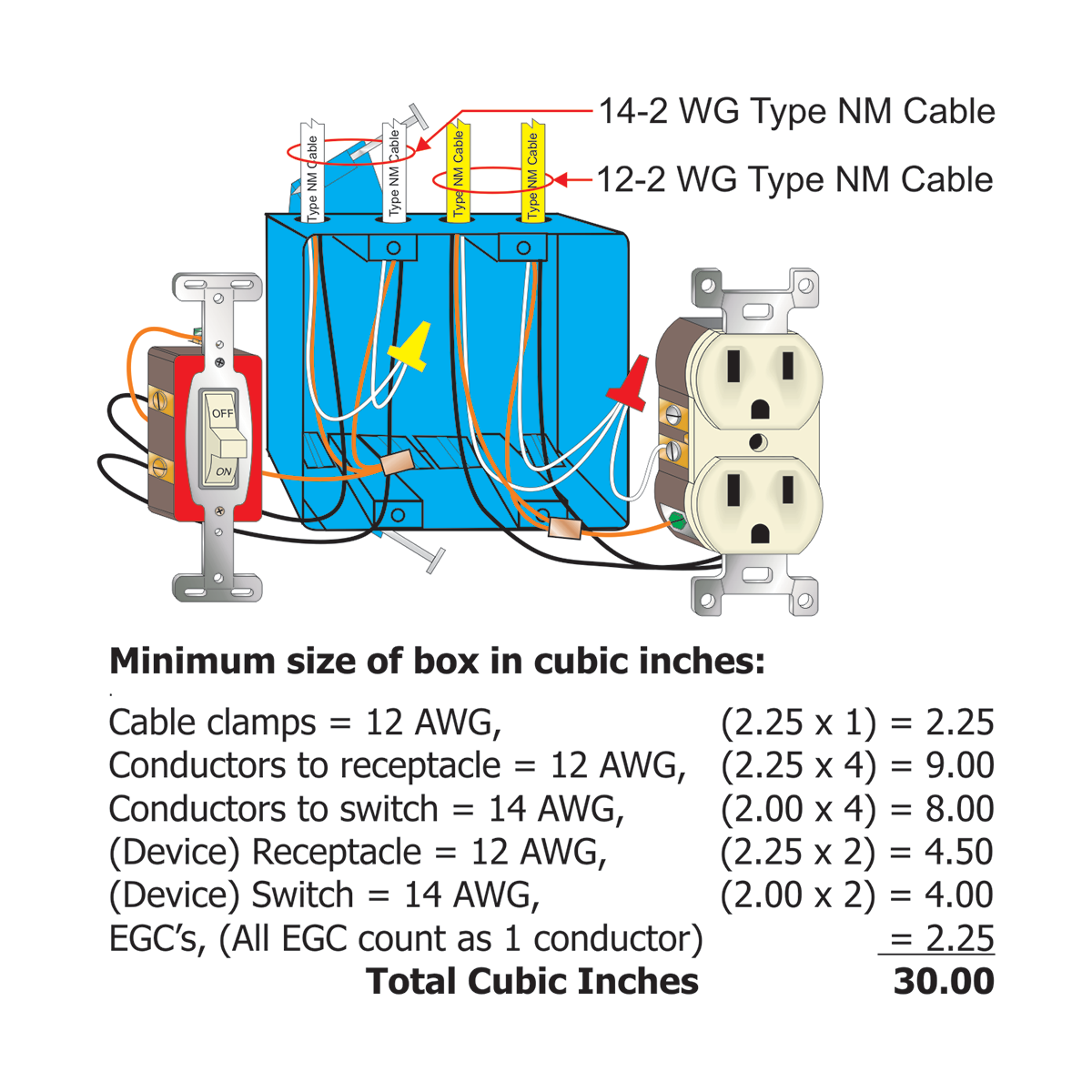
Each device or equipment is considered individually where more than one item is contained in the box. For example, if a switch has 14 AWG wire connected to it, a volume allowance of 2 x 2.0 cubic inches or 4 cubic inches is required. If a receptacle has 12 AWG wire connected to it, a volume allowance of 2 x 2.25 or 4.5 cubic inches must be made for that particular device.
Any device or utilization equipment wider than a single 50 mm (2 in.) device box is required to have a double volume allowance provided for each gang required for mounting. This would apply to a device such as a dryer receptacle that would require two yokes for mounting. A device such as this would be required to be counted as four conductors based on the largest conductor connected to such device.
Equipment Grounding Conductor Fill
Requirements for equipment grounding conductor and equipment bonding conductor fill are covered in the Code. A single volume allowance is made regardless of the number of equipment grounding conductors installed. The allowance is based on the largest equipment grounding or equipment bonding conductor present in the box. Where an additional set of equipment grounding conductor(s) is present in the box, such as an isolated equipment grounding conductor for an isolated receptacle as permitted by NEC 250.146(D), an additional volume allowance is required based on the largest isolated equipment grounding conductor(s) in the additional set.
Conclusion
As this article has demonstrated, several factors must be taken into consideration when determining the maximum number of conductors a box is allowed to contain without creating a Code violation. Are cable clamps involved? How many devices will be installed in the box along with these conductors at final installation? These are just some of the questions that must be answered to arrive at a compliant installation for box fill. Deduction for cable clamps, devices, barriers, etc. is also why you cannot go with the simple information provided in Table 314.16(A) for the maximum number of conductors a particular sized box can contain. As stated previously, these contained conductors must have ample free air around the conductor and its insulation to allow proper dissipation of self-generated heat from the conductor itself.
Proper box fill calculations is a vital cog in the safe installation of the electrical wiring installed in commercial and residential buildings. I can testify that checking for box fill provisions will eventually become second nature to the inspector and the installer if they make it a normal part of their daily inspection or installation routine. It might be cumbersome at first, but eventually, a box that contains too many conductors will jump off the wall at you if you make box fill calculations an everyday normal practice.