 The following questions and answers result from some of the more common situations that many inspectors face throughout their working day when seeing a new PV installation or reviewing a set of plans for a PV system. The questions are simplified versions of questions I receive in e-mails and from questioned plan sets as well as sometimes long, involved phone calls.
Service Entrance Questions
Question: I am looking at a diagram of a PV system where the main service is a 100-amp main-lug-only (MLO) panel with six breakers. One of the six breakers is rated at 40 amps and is being backfed from a utility-interactive PV inverter. Doesn’t this 40-amp breaker exceed the 120% allowance of 690.64(B)/705.12(D) that would limit the backfed breaker to 20 amps on a 100-amp panel?
Answer: These six breaker MLO service-entrance panels are common in many areas of the country, primarily in older homes. There is no main overcurrent device or disconnect ahead of the MLO panel busbar, so each of these six breakers represents a service disconnect. That backfed 40 amp represents a supply-side connection allowed under 690.64(A)/705.12(A) and the load-side requirements of 690.64(B)/705.12(D) do not apply. The limit of the breaker rating in such a supply-side connection would be the rating of the MLO panel, the rating of the panel busbar (usually the same as the panel rating), or the rating of the service, whichever is less.

Photo 1. Main-lug-only panel — PV breaker rating?
Question: The PV installer has made a supply-side connection between the meter base and the load center by cutting the EMT, installing a pull box and making the PV connection inside the box. He has installed a fused disconnect adjacent to the pull box and has run EMT to the inverter. Workmanship looks good, but what else should I be looking for?
Answer: The NEC treats these supply-side connections as additional services as allowed by 230.2(A)(5). As services, the various requirements of services should be followed including conductor type between the connection point and the disconnecting means, routing and protection of this service-entrance conductor, bonding neutral to ground at the new service disconnect, and running a grounding electrode conductor from the bonding jumper to the existing grounding electrode. Yes, it appears that there may be some parallel paths for the neutral currents, but they do not appear objectionable since similar multiple bonding jumpers in close proximity are shown in Article 250 in the NEC Handbook where multiple services are involved.

Photo 2. Utility-required disconnect — PV AC disconnect too?
Question: We have numerous commercial buildings in our jurisdiction with 480-volt, 4-wire services that are over 1000 amps and have main service-entrance disconnects as main breakers with attached or internal ground-fault protection devices. What are the issues that should be considered when looking at a plan to backfeed a panel on the load side of this main GFP breaker with the output of a photovoltaic inverter?
Answer: Briefly: (1) Has the GFP device been evaluated for backfeeding? Most new ones are, but older units may not have been evaluated. UL does not do this particular evaluation; only the manufacturer can provide the necessary information. The breaker may not be marked “Line” or “Load,” which indicates that it has been evaluated for backfeeding, but this has no bearing on the suitability for the GFP device for back feeding. (2) Does the inverter ac output circuit have a ground-fault protection device connected to protect loads from ground-fault currents originating from the inverter? The internal dc ground-fault protection device does not meet this function. (3) Has a fault analysis been accomplished to determine how ground-fault currents will divide between the main GFP and the inverter GFP and what the proper trip settings for each should be? See a White Paper on this subject on the author’s web site below.

Photo 3. Inverters with internal AC and DC disconnects plus external disconnects
Disconnect Questions
Question: Can an unfused disconnect used to meet a local utility requirement be also used as the 690.15 maintenance disconnect for the inverter? The disconnect is not locked by the utility and is located near the service disconnect and the meter on the outside of the building.
Answer: Usually the utility will have no objections to this dual use of the utility-required disconnect, but it never hurts to verify. In order to meet the intended safety requirements of 690.15, the disconnect should be located near or at least within sight of the inverter. This location requirement would allow the inverter to be maintained in a safe manner by opening this ac disconnect, opening the dc disconnect, verifying that both are open and then working on the inverter as necessary. An inverter that is not mounted within sight of this utility-required disconnect may require that an additional ac disconnect be mounted adjacent to the inverter location.
Question: Can the disconnects, either ac or dc or both, that may be internal to the inverter be used as the 690.14 dc PV disconnect and/or the 690.15 required disconnects?
Answer: If the inverter is mounted in the location required by 690.14 for the dc PV disconnect, an internal dc disconnect might meet that disconnect requirement. However, meeting the 690.15 maintenance disconnects with any internal disconnects may pose certain problems. This is a discussion that the PV installer and the AHJ will have to have. Where the internal disconnects are mounted in a section of the inverter that is separate from the inverter electronics and the inverter electronics section can be removed for service while the disconnect section remains attached to the wall and the dc and ac conduits, then it would appear that the safety intent can be met. However, if the internal disconnects are in one enclosure with the inverter proper, there is the possibility that a less-than-fully-qualified person might run into trouble by unintentionally pulling live dc cables through the conduit knockout when removing the inverter for service. Recent internal disconnect failures, a few disconnect fires, and recalls of some inverters for problems in the disconnect section have caused many AHJs to reevaluate their position on the internal disconnect.

Photo 4. Microinverters — disconnects required?
Question: Microinverters are mounted on roofs in not readily accessible areas. How can the disconnect requirements of 690.14 and 690.15 be met? It would appear that 690.14(D) would apply since the inverters are mounted in these roof top areas, but there are no disconnects being used. Should I require ac and dc disconnects for each microinverter?
Answer: Before requiring large and expensive ac and dc disconnects for each inverter, check with the microinverter manufacturer to determine if the connectors on the microinverter have been evaluated as load-break-rated disconnects. While the typical MC 3 or MC 4 PV disconnect on a PV module is only a recognized component because it cannot pass the listing requirements at 600 volts dc, those connectors can be evaluated as load-break disconnects at the lower operating voltages (typically less than 80 volts) of the microinverters. At least one manufacturer of microinverters has had the ac and dc connectors so evaluated.

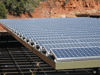
Photo 5. FMC from the roof
Where an additional ac disconnect is deemed necessary, the common 60-amp pullout ac HVAC unfused disconnect can meet the requirements and provides a transition point between the microinverter cable and the circuit to the ac panel. It is usually cheaper than many other outdoor-rated pull or junction boxes.
Circuit Questions
Question: The electrician ran flexible metal conduit from the roof penetration through the house to the dc disconnect and the inverter located in the basement. Is this type of installation permitted per the NEC?
Answer: Yes, as of the 2005 NEC, Section 690.31(E) allowed metal raceways to be used for this interior circuit run between the rooftop mounted PV system and the readily accessible dc disconnect/inverter. This would include flexible metal conduit (Type FMC). In the 2011 NEC, a metallic cable assembly, Type MC was added. Type AC metallic cable assemblies, particularly those with aluminum outer jackets, are not approved or listed for use in direct current (dc) circuits.
Question: Is the inside of a house or building with locked doors and windows considered a readily accessible location for meeting the Article 230 service entrance and Article 690 PV disconnecting means location requirements?


Photos 6A and 6B (inset). Steel door and high security lock — readily accessible?
Answer: Excellent question, and one that needs further clarification in the Code. Fire fighters will usually call the utility to have the ac power disconnected from a building before entering an area that might have energized circuits. When the utility is unable to get to the location in a timely manner, the fire fighters are reluctant to remove the utility meter due to the safety hazards and legal issues involved. In life safety issues, they will pull the utility meter thereby de-energizing the ac circuits.
But what about that inside-the-house dc disconnect for the PV system? They know that it is there because of the code-required directories and placards on the outside meters and service equipment. Fire fighters have told me that they have master keys for many locks; and for the high security locks, there is always the fire axe. However, the answer to this question remains unclear in the NEC. Is the inside of a locked building considered a readily accessible area in which an ac service-entrance disconnect or a dc PV disconnect can be located?
Question: Section 690.47(C)(3) in the 2011 NEC allows the function of the PV inverter dc grounding-electrode conductor to be combined with the function of an inverter ac equipment grounding conductor in a single conductor meeting the most stringent requirements of either conductor. In many older electrical systems and in some newer ones, an outbuilding such as a barn or garage is connected to the main service panel with a feeder that uses the neutral as both the grounded circuit conductor and as the equipment grounding conductor as allowed by 250.32(B) Ex. If a utility-interactive PV system is installed on the outbuilding, can that combined neutral/ac equipment grounding conductor be used as the 690.47(C)(3) “grounding” conductor for the inverter?
Answer: Section 690.47(C)(3) addresses only the grounding-electrode and equipment grounding conductors from the inverter. Under normal operation, neither of these conductors carries current, whereas the combined ac neutral/equipment grounding conductor allowed by 250.32(B) Ex would normally be a current-carrying conductor. Although the NEC does not explicitly address this combination, I tend to think that these two functions should not be further combined into a single conductor in that feeder between the main panel and the outbuilding. One reason that comes to mind is that lightning surges induced from the PV array now have a relatively easy path along the neutral into the service equipment. However, the next question may have some bearing on this issue.
Answer: Although 690.47(C) in the 2008 is a bit murky, I believe both editions of the Code allow this combined conductor to be terminated at a grounding bus bar in the nearest ac panel that has an ac grounding electrode conductor connected to a grounding electrode that meets the requirements of the Code. Such a panel would certainly include the main service-entrance panel and also any feeder panel that has the necessary grounding. With respect to the previous question, the remote building that has the 250.32(B) Ex “grounding” system is required to have a grounding electrode at the outbuilding. It would appear that the PV inverter could be mounted in this location with the combined dc grounding electrode conductor/ac equipment grounding conductor terminated at the grounding bus bar in the outbuilding panel. In this case, the combined neutral/equipment grounding conductor between the buildings would not be involved in the inverter grounding requirements.
Ratings and Calculations Questions
Question: I’m a building inspector and I have a few questions regarding STC ratings. I know that the NECrequires all PV modules to be marked with its maximum voltage, open-circuit voltage, short-circuit voltage, etc., and common sense will tell me that the conductors and OCPD must be sized based on that info. The problem is, I can’t find anywhere in the NEC that states exactly that, other than the word “rated” in 690.8 and 690.9. So I guess I’m asking: What forces us to use STC ratings when sizing a PV system? And are STC ratings the only ratings marked on modules? If another testing standard was marked on the modules and the modules were listed, would the Code require the wires and OCPD to be sized based on that info instead of STC?
Answer: The key is NEC Section 110.3(B), which requires that we use the instructions and labels on a listed product. The label on the back of a PV module is required by UL Standard 1703 and the values on that label are based on testing under the Standard Test Condition as required by the standard. As far as I know, UL Standard 1703 is the only standard being used in the U.S. to certify/list PV modules and that standard is being harmonized with the European IEC standards. In both the UL and the IEC standards, Standard Test Conditions are used to rate the module. NEC Informative Annex A lists UL Standard 1703 as the applicable standard for flat plate PV modules. There are no values on the back of the module other than the STC values. So, the rated values required in 690.8 are the values marked on the back of the module and they would be used in the circuit sizing and overcurrent protection. In a similar manner, the motor nameplate ratings in terms of locked-rotor current and full-load current would be used in determining the circuit sizing for that motor. Yes, there are other specifications sometimes listed for modules in the technical specification sheets or in other documents. For example, the temperature coefficients are listed in specification sheets and used to calculate the cold weather, open-circuit voltage as required by 690.7. In some cases, PVUSA Test Conditions (PTC) are given, but these typically are used for performance estimations and are not involved with Code calculations.

Photo 7. Cold weather Voc calculations are important.
Question: I am checking a set of plans for the calculations on the cold-weather open-circuit voltage (Voc) and I find that some of the module specification sheets show a Voc temperature coefficient in degrees K. In the January-February 2009 IAEI News article on “PV Math,” you described the method of using coefficients with degrees Celsius (C). But what do I do with these numbers in degrees K?

Answer: You use the numerical values in coefficients that are based on degrees Kelvin (K), in the same way you use the coefficients based on degrees Celsius (C). A change in temperature of one degree K is the same as a change in temperature of one degree C. The difference is that the Kelvin temperature scale is based on zero being at an absolute zero temperature where all molecular motion stops, but the Celsius temperature scale has a zero based on the freezing point of water. The zero point on the scale does not affect our calculations.
For Additional Information
See the web site below for a schedule of presentations on PV and the Code.
The Southwest Technology Development Institute web site maintains a PV Systems Inspector/Installer Checklist and all copies of the previous “Perspectives on PV” articles for easy downloading. A color copy of the latest version (1.91) of the 150-page, Photovoltaic Power Systems and the 2005 National Electrical Code: Suggested Practices, written by the author, may be downloaded from this web site: http://www.nmsu.edu/~tdi/Photovoltaics/Codes-Stds/Codes-Stds.html
And, yes, it may be updated to the 2008 and 2011 Codes sometime this year.