
Well here we are at the close to yet another year and as always our success can be measured by all of the great things we’ve accomplished that increased electrical safety in our industry. Now is the time to reflect on our successes, our failures, and to start making our plans for 2016. Before you know it, 2016 will be upon us, so we had best be prepared.
There are those common basic details that seem to cause a lot of problems and get missed by even the most seasoned professionals. It is unfortunate that the challenges are often with the basics. The call to order is to regain focus on the basics in 2016. After all, it’s all too often the basics that wrap a job around the axle and cause delays and costs to contractors, owners, and manufacturers to complete a project. Consider an effort in 2016 to get back to the basics of electrical distribution system design whether it is residential, commercial or industrial. There is a lot that can be revisited. We’re in a target rich environment.
Some Common Overlooked Items
As I speak with inspectors and installers, these are some of the areas that I have seen being missed during design and installation that lend for some difficult phone calls, texts, and emails as projects are held up during the final days and throughout the inspection process. These present a good place to focus in 2016.
Nameplates
It doesn’t get any more basic than simply reading nameplates of electrical equipment, understanding them, and determining key parameters necessary for performing such basic tasks as sizing conductors and overcurrent protective devices. Nameplates on electrical equipment all too often may leave more questions than answers. At times, they aren’t read at all until the electrical inspector does a review and catches problems. The drawings may not match the installation. Electrical loads will carry either an official nameplate or other label of some sort with information that is critical for such National Electrical Code (NEC) related topics as load calculations, short-circuit calculations and ensuring products are applied within their ratings. Sometimes the label itself will specify a minimum or maximum upstream overcurrent protective device size or even the specific upstream overcurrent protective device that is required to achieve the ratings of the equipment being installed. Distribution equipment like transformers will carry nameplate or label information such as impedance that is critical for short-circuit current calculations. Even a transformer nameplate can leave us scratching our head.
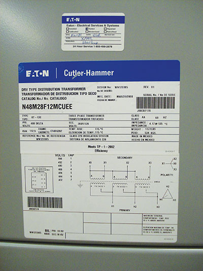
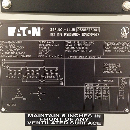
Transformer kVA: The transformer label shown in figure 2 is a good example. Focus your attention on the voltage taps that indicate the primary voltage for each tap position. The primary voltage will be dependent upon the installed tap configuration. Increasing the primary voltage by 2.5% will decrease the FLA by 2.5% and decreasing the primary voltage by 2.5% will increase the FLA by 2.5%. Tap changing is used when primary voltages are different from that which is required for the loads; but it does beg the question of whether or not we need to take them into consideration when sizing primary and secondary conductors. The same goes for those transformers that may have more than one KVA rating as shown on the nameplate of figure 3. Multiple kVA ratings address added cooling fans that can occur either at first installation or later as the FFA rating, Future Fans Added, implies. The simple/basic topic of calculating the full load amps (FLA) of a transformer can get complicated in a hurry, but at least the nameplates include all of the information necessary to begin our journey. It could be, as in other cases, the information we need is not even on the equipment.
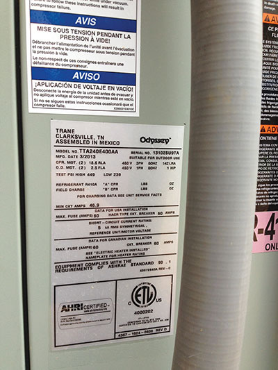
SCCR Ratings: Section 110.10 requires electrical equipment to have a Short-Circuit Current Rating (SCCR) greater than the maximum available fault current available at the point at which it is installed. This requirement is an interesting topic as electrical distribution equipment is, or at least should be, equipped with information that tells us how it performs when very high short-circuit currents flow through them. SCCR information on labels may or may not be a challenge to locate. Another challenge may lie in knowing whether or not specific equipment has to have an SCCR rating. Not all long ago, I was presented with the question of the SCCR rating of a GFCI receptacle. A really good electrical inspector flagged a device on a project due to the available fault current exceeding its SCCR rating. That’s when the basics came up and bit me—one of those basic technical details that is easy to miss. Figure 4 is a good example of a label that contains the information you need to determine whether Section 110.10 is met. In this example, the equipment is clearly able to handle no more than 5 kA of available fault current. Other equipment—such as lights, ceiling fans, cook tops, dimmer switches, and probably many other examples—may leave us questioning whether or not we even have to consider SCCR.
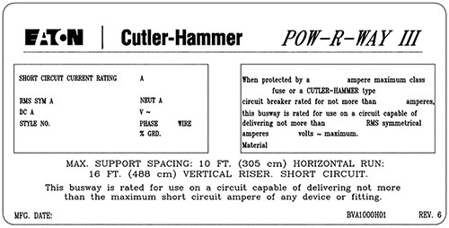
There are those products that achieve an SCCR rating because of a specific overcurrent protective device directly upstream in the circuit. The image in figure 1 is an example of a busway label that has the provisions for labeling the SCCR of this equipment and the conditions upon which the equipment has achieved this specific rating. Equipment that achieves higher SCCRs may do so because of specific overcurrent protective devices upstream. Attention to this detail can make a big difference. I relate the example of a non-fused disconnect switch commonly found as a bypass for service-entrance meters. When you read the literature on these devices, you may mistakenly think that you have just installed a non-fused disconnect with a rating of 100 kA SCCR. A closer look at the product literature reveals that the 100 kA SCCR of that equipment is only achieved with a specific fuse upstream or as part of the disconnect.
Load Calculations
I must admit that I don’t do as many load calculations as I used to; and even back then, I probably didn’t do as many as some do in our industry today. I can say that I have seen calculations that illustrate how little some know about this important calculation. Continuous and non-continuous load identification can be a challenge and an area where debates ensue. The NEC offers two methods to calculate dwelling unit service and feeder loads. One can take the Standard Calculation route as found in Article 220 Part III or take the Optional Calculation route as found in Article 220 Part IV. Annex D provides examples of both methods. I have seen some individuals state that there is a maximum number of receptacle outlets that can be installed on one branch circuit, and state that they do not want to overload the circuit. Then you have the situations where the optional calculation route was taken, and the service sized just above the calculated load, only to find later that items such as ceiling fans and other similar loads were not included in the calculation. These issues found too late can cost time and money, let alone project delays.
Available Fault Current
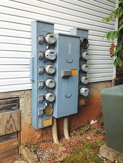
I have said this before in more than one of my articles, but I will say it again; the short-circuit study is one of the most fundamental calculations performed on a power distribution system. The NEC presents us with Section 110.24 that requires the marking of the maximum available fault current at the service-entrance equipment. Some may think that we don’t have to calculate fault currents any further down into the distribution system than the service. The installation shown in figure 5 is such that the large green object in the image to the right is the utility supplied transformer that has 34,792 amps line-to-line and 69,583 amps line-to-neutral available at its load-side terminals. Taking into consideration the short conductor run of 2-500 kcmil conductors in PVC conduit, this electrical service meter equipment is looking at a maximum of 52,500 amps of available fault current. If we do not calculate the maximum available fault current for an installation, it is challenging, if not nearly impossible, for the inspector and the installer to determine if the equipment is being applied within its rating.
Service-entrance equipment is not the only place we need to understand our available fault-current values. Further down the system we may have such equipment as busway, power distribution blocks, transfer switches, industrial control panels, and more that will have short-circuit current ratings and, in the case of panelboards and switchboards, that include OCPDs that have interrupting ratings that must exceed the maximum available fault current. A product applied outside of its rating is not healthy for anyone involved. This fundamental calculation of short-circuit current is yet another one of those basics that, unfortunately, in many cases I have witnessed, gets completed incorrectly—if completed at all.
Terminations
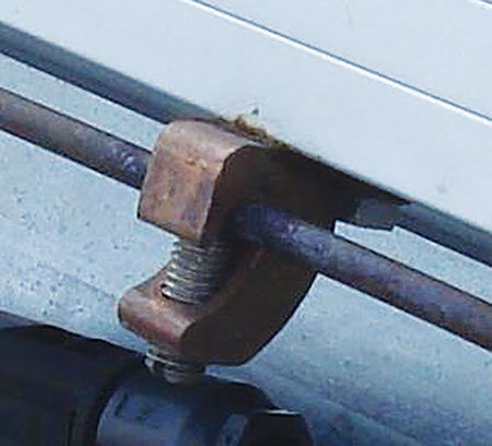
I was asked one time to do a two-hour program on terminations; I scratched my head wondering how I would ever fill two hours on this topic when in reality I needed more time and not just because I’m long winded. Terminations seem like a simple basic task, but in reality it is not only a complex topic that can cause many hours of troubleshooting, it is also that job on the site that is often given to the most inexperienced individual on the team. The image in figure 6 was taken on a rooftop PV installation that to my eye looked impeccable. The inspector with whom I walked advised me to put my hands in my pockets and not touch anything metal and then pointed out all of the bonding problems with the installation that my eye never caught. He pointed out incorrect lugs, holes drilled in frames of the panels that voided the UL listing of the product, and many more issues that, again, I probably would never have found. Bonding and terminations are just one more example of basics that are not being done correctly in the field.
Dry, Wet and Damp Locations
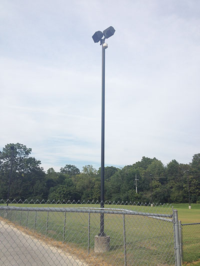
So we can all read the definitions in the NEC that tell us what dry, wet and damp locations are but they may not be that easy to spot in the field. I recently purchased a home in St. Louis, Missouri, as I moved into a new position with Eaton; and the home inspector flagged a ceiling fan in the bathroom, noting that the ceiling fan was not rated for a “Wet” location. I had to scratch my head and ask whether the bathroom is a really a wet location for a ceiling fan. Figure 7 presents another good example and, for some, a challenge to determine if the base of a light pole is a wet, damp, or dry location—yet another basic topic that can use more exploration.
Your Safety Checklist
So I will end with just a word of encouragement to dust off your safety plan and get ready to review yet again for 2016. Your safety plan is to increase safety, but it requires you to establish budgets and properly fund the effort. Personal protective equipment (PPE), tools, procedures, and education, are all important to meet your safety goals. Set your budgets for next year and make sure you address your safety plan needs.
If you don’t have a safety plan, ask yourself why that is. Without a plan, you are flying by the seat of your pants. As always, keep safety at the top of your list and ensure you and those around you live to see another day.