Electrical systems and non-current-carrying metal parts of equipment in an electrical installation generally are required to be grounded; however, alternatives are given within the NEC that relax the grounding rules for equipment. These alternatives include isolation, insulation, or guarding as methods of providing equal and effective safety measures without grounding the metal parts or equipment. It is important to meet all of the provisions of the Code when utilizing any of these alternatives.
Electrical systems and associated metal equipment, such as metallic raceways and cables, are grounded as required; however, some electrical systems are not required to be grounded but are permitted to be operated grounded or ungrounded. Whether systems are grounded as a requirement of 250.20 or grounded by choice, all of the rules for grounded systems must be followed. When a system is grounded, one conductor of the system itself is intentionally grounded. When equipment is grounded, it is connected to the earth or some conducting body serving in place of the earth to minimize differences of potential between the metal component and the earth.
Grounded is defined in Article 100 as “Connected to the earth or to some conducting body that serves in place of the earth.”
Grounding electrode is not defined in the Code but can be described as: “”A conducting element used to connect electrical systems and/or equipment to the earth.”” The grounding electrode establishes a connection to the earth of lowest practical impedance to put system-grounded conductors and metal equipment of the system at earth potential.
Function
The earth is considered to be at the potential of zero, the potential one tries to achieve when grounding or earthing systems and metal equipment associated with the system. The primary purpose of the grounding electrode is to establish and maintain the electrical equipment and any grounded system conductor at the potential of the earth at the grounding electrode connection to the earth. The grounding electrode has little or no affect in facilitating overcurrent device operation and should never be relied upon for this purpose. To rely on the grounding electrode and the earth to serve as a low-impedance return path to the source is a serious misapplication and violates fundamental principles of safety.
Another essential function of the grounding electrode is to dissipate overvoltages into the earth. Overvoltages can be caused by different events that occur, such as high-voltage conductors being accidentally connected to the lower-voltage system by a failure in a transformer, by an overhead conductor dropping on the lower-voltage conductor, or from lightning strikes in the vicinity of the electrical system and equipment.
Section 250.24(C) requires the equipment grounding conductors, the service-equipment enclosures, and, where the system is grounded, the grounded service conductor to be connected to a grounding electrode. The conductor used to make this connection is the grounding electrode conductor.
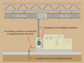
Figure 1. When supplementary electrodes are installed, they also must be connected to the equipment, which is connected to the required equipment grounding conductor
Supplementary Electrode
When something is supplementary to another, it usually indicates that both are used to achieve one goal. For example, if the amount of vitamins one takes is shown to be inadequate for minimum daily requirements, a vitamin supplement can be used to provide the amount desired, but vitamins cannot serve in place of normal food consumption.
Although the term supplementary electrode is not defined in the NEC, it can be thought of as an electrode that is over and above the minimum requirements of the NEC, an addition to any safety grounding or bonding circuit of the electrical installation. Supplementary electrodes serve to make a connection to the earth that is local to the equipment needing the supplement. It is imperative that the required equipment grounding conductor remains connected to the equipment also. This is reinforced by the mandatory provision that the earth shall not be used as the sole equipment grounding conductor. This language is found in 250.4(A)(5), 250.4(B)(4), and 250.54.
Example Installations
An example of supplementary grounding electrode is a grounding electrode installed at a light pole base in a parking lot. This grounding electrode at the pole base serves to connect the metal pole to the earth and the equipment grounding conductor at that location. TheNECdoes not require this electrode, but does provide minimum rules when such electrodes are installed. The electrode serves to put the metal pole at the earth potential at the pole location and supplements the required equipment grounding conductor connected to the pole. Another ancillary function of this electrode includes dissipation of lightning strikes on the lighting pole by providing a direct path for the strike into the earth at the pole location, thus enhancing system safety and personnel safety.
Another example of a supplementary electrode is an electrode that would be installed in the local vicinity of sensitive electronic equipment. This electrode installation is generally installed as an option or as a recommendation by a manufacturer of the equipment and is primarily directed toward performance. When such electrodes are installed, they also must be connected to the equipment, which is connected to the required equipment grounding conductor (see figure 1). Electronic data processing equipment is not permitted to be operated ungrounded or by connection to only its own grounding electrode.
Section 250.52 provides a list of electrodes that are permitted to be used when grounding electrical systems and/or equipment. A change in the 2002 edition of the Code removed the word made in reference to certain grounding electrodes. Generally, the electrode is not made by the installer but rather installed. One of the more common supplementary grounding electrodes is the familiar grounding rod. Where a ground rod is installed, it is required to be in contact with the earth for a minimum of 8 ft. Alternative provisions are provided to accomplish ground rod installation when rock bottom is encountered.
Down to Earth
The NEC provides minimum provisions in this case and many supplementary ground rods used for sensitive electronic equipment far exceed these rules. The important item to remember is safety first, then enhancements directed toward electronic equipment performance. Generally speaking, a premises wiring system that meets the requirements of the NEC relative to grounding and bonding will be a stable platform in which to provide grounding enhancements. It is common in the IT industry to be concerned with power quality issues. Many power quality organizations insist on a thorough grounding and bonding system analysis prior to application of filtering equipment.
It is common during the grounding and bonding system analysis to discover grounding and bonding connections in locations other than those permitted by the Code that require correction prior to any effective application of noise filters to the system. During these surveys, supplemental grounding electrodes are often discovered and improper connections to these electrodes are revealed. It is important to get back to basics at this point and the basics in this sense has to include verification that equipment grounding conductors (safety grounds) are always connected. Safety first, then work on enhancing equipment performance. This does not discount the importance of reducing data errors due to RF interferences and EMI in the grounding circuit(s), because these are critical issues also. It is always better to approach this situation with the best of both worlds in mind. One should not be installed without the other.
Isolated Grounding Circuits
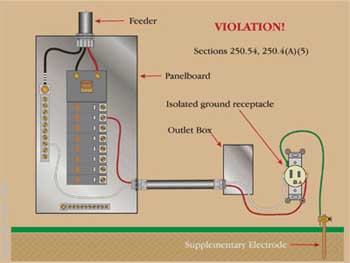
Figure 2. A closer inspection reveals that the isolated equipment grounding conductor was installed and connected to the receptacle, but was routed directly to a ground rod
TheNECincludes provisions for installation of isolated equipment grounding conductors for the reduction of electromagnetic interferences in electronic equipment. In these provisions, it is clear that the earth shall not be used as the sole equipment grounding conductor. A situation once came up where I was checking the polarity of an isolated grounding type (IG) receptacle installed for a cash register and found it to read “no ground.” A closer inspection revealed that the isolated equipment grounding conductor was installed and connected to the receptacle, but was routed directly to a ground rod. This is not considered an isolated grounding conductor for the purposes of 250.146(D) or 250.96 (see figure 2). In this case, the earth was relied upon for the equipment grounding conductor (safety ground). A ground fault would attempt to flow through the earth to the source, but would be limited by this high impedance path. This is a common and serious violation that can be attributed to lack of knowledge of the purpose of grounding and bonding.
Rod Pipe or Plate Electrodes
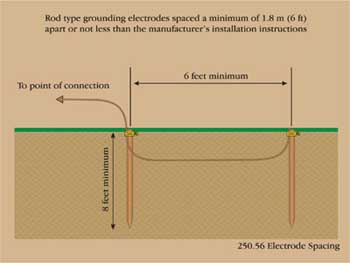
Figure 3. Electrodes consisting of a rode, pipe, or plate that do not have a resistance to ground of 25 ohms or less must not be installed less than 1.8 m (6 ft) apart or less than indicated in the manufacturer’s installation instructions, if applicable
Where a rod, pipe or plate electrode is installed for a system or service due to the lack of any electrodes required by 250.52(A)(1) through (A)(4), it is required to have a resistance of not more than 25 ohms-to-ground. Where the resistance is in question, an additional electrode can be installed and at that point no maximum resistance would be required.
Resistance of installed rod, pipe, or plate electrodes is important and applicable to these types of electrodes when installed as a requirement of the Code. “A single electrode consisting of a rod, pipe, or plate that does not have a resistance to ground of 25 ohms or less shall be augmented by one additional electrode of any of the types specified by 250.52(A)(2) through (A)(7).”1 These electrodes must not be installed less than 1.8 m (6 ft) apart or less than indicated in the manufacturer’s installation instructions, if applicable. “The paralleling efficiency of rods longer than 2.5 m (8 ft) is improved by spacing greater than 1.8 m (6 ft)”2 as the possibilities of their effective resistance areas overlapping are reduced (see figure 3).
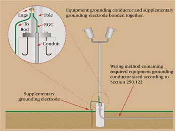
Figure 4. Generally, an additional supplementary electrode is connected to the equipment at the same location where the equipment grounding conductor is connected to the apparatus
Electrodes installed as supplementary do not have to meet the maximum resistance to ground requirements of 250.56 or the requirements for bonding all electrodes together as indicated in 250.50 and 53(C). Typically, when an additional supplementary electrode is installed, it provides ground reference local to the equipment to which it is connected. Generally, it is connected to the equipment at the same location where the equipment grounding conductor is connected to the apparatus (see figure 4).
Supplementary Electrodes Compared to Supplemental Electrodes
Unlike supplementary electrodes covered by 250.54, the supplemental electrodes referred to in 250.53(D)(2) are required where an underground metal water pipe is used as the electrode required by 250.50
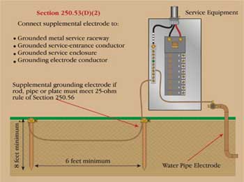
Figure 5. Where the supplemental electrode is a rod, pipe, or plate type, it should comply with 250.56 for maximum resistance or an additional electrode can be installed
“A metal underground water pipe” electrode for a system or service “shall be supplemented by an additional electrode of a type specified in 250.52(A)(2) through (A)(7). Where the supplemental electrode is a rod, pipe, or plate type, it shall comply with 250.56 for maximum resistance or an additional electrode can be installed. The supplemental electrode shall be permitted to be bonded to the grounding electrode conductor, the grounded service-entrance conductor, the nonflexible grounded service raceway, or any grounded service enclosure”3 (see figure 5).
“Where the supplemental electrode” for the water pipe “is a rod, pipe, or plate electrode, that portion of the bonding jumper that is the sole connection to the supplemental grounding electrode shall not be required to be any larger than 6 AWG copper wire or 4 AWG aluminum.…”4
Part III of Article 250 covers the requirements for grounding electrodes and the grounding electrode system. The electrode system for a service or system is specified in 250.50. The electrodes permitted to be used for grounding services or systems are included in 250.52(A). Electrodes covered by 250.54 overlay the required grounding electrodes for a service or separately derived system. Grounding electrodes should never be used as the only safety grounding circuit for equipment. The earth is a high impedance path and shall not be used as the sole equipment grounding conductor as indicated in 250.54. Supplemental electrodes are permitted by the Code, but their installation must be in addition to the required safety grounding circuit (the equipment grounding conductor) and should not affect the safety of the circuit or system. It serves to enhance the required grounding and bonding circuits.
Always refer to the local authority having jurisdiction for any local requirements or when in doubt as to the minimum requirements for supplementary grounding electrodes or what to look for when installing or inspecting these types of grounding connections. It never hurts to ask when in doubt.
1 NFPA 70,National Electrical Code, 250.56 Resistance of Rod, Pipe, and Plate Electrodes, (National Fire Protection Association, 2002). 70-106.
2 NFPA 70, 250.56 FPN, 70-106.
3 NFPA 70, 250.53(D)(2), 70-105.
4 NFPA 70, 250.53(E), 70-105.