To explain the difference in grounding and bonding to me, a sage mogul once used the analogy of a marriage. He explained that “grounding and bonding are like a wedding…when two people get married, they are bonded together as one! Then after a little while, the husband gets grounded!” While this tale (if not entirely true) was entertaining, it did nothing to take the mystery out of grounding and bonding for me.
Perhaps nowhere in the Code is this mystery more prevalent than at 680.26 dealing with equipotential bonding for swimming pools and similar installations. I would nominate this NEC section as one of the most misunderstood and misinterpreted sections in the entire Code. Historically, this section is one of those that go through some of the most dramatic revisions from Code cycle to Code cycle. In this article, we will attempt to take the “mystery” out of this one area for equipotential bonding for swimming pools and similar installations.
Equipotential Bonding Requirements
Bonding requirements are an important and unique protective method employed to increase the safety of the users of bodies of water such as pools, spas, and hot tubs. Bonding connects the conductive elements of the pool structure, nearby metallic objects, and electrical equipment enclosures together. Bonding is required to eliminate voltage gradients (rises in voltage potential) in the pool area. When metallic parts are bonded together, they effectively eliminate differences of voltage potential that may exist between the individual conductive parts and thus reduce the shock hazard. If these metallic conductive parts are not bonded together, this leaves these conductive parts having the potential of being at different voltage potentials. In a case like this, the human body can serve as a “conductor” between two conductive parts at different voltage potentials if contact is made with these conductive parts. If a conductive path is provided between two conductive parts at different voltage potentials, this current is going to naturally equal itself out between these conductive parts. An electrical shock occurs when the human body is used as the “conductor” between these conductive parts. If these conductive parts are mechanically, electrically, and intentionally bonded (married) together, there is typically no shock hazard present as these conductive parts are always at the same voltage potential.
This bonding is referred to as equipotential bonding [NEC 680.26(A) and (B)]. Once called the “common” bonding grid, it was changed to “equipotential” bonding during the 2005 NEC to help clarify and describe the function and purpose of this section.
Now is a good time to explore the different purposes served by bonding and grounding and to develop a clear understanding of the two terms. Bonding is used to equalize voltage potential differences to reduce shock hazards between different parts of the pool by connecting potentially conductive parts together. Grounding involves providing a low-impedance, ground-fault return path from the equipment required to be grounded back to the source of the electrical system, typically through the equipment grounding conductor routed with the branch-circuit conductors. This path facilitates the operation of the fuse or circuit breaker to allow it to remove the faulted condition. In short, bonding means “connected together,” while grounding means “connected to earth.” Grounding and bonding together provide the safety from shock hazards that is so important, particularly in an aquatic environment such as a swimming pool.
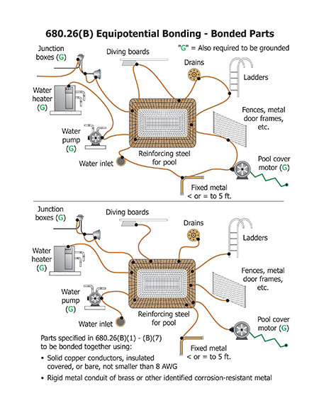
Since several types of electrical equipment commonly used with swimming pools, hot tubs or spas that are bonded together must also be grounded, an interconnection between the grounded (neutral) conductor and bonding grid exists. This interconnection, usually at the electrical service equipment, is often remote and is not intended to play a part in equipotential bonding (see figure 1).
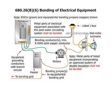
Figure 1. Bonding and grounding of pool associated components and equipment
Swimming pools, spas, and hot tubs present special shock hazards to people.
The water is mixed with chemicals, which often increase conductivity.
People are in direct contact with the water and encounter grounded objects such as metal ladders.
Electrical equipment is used to circulate and heat the water and for other related functions such as illumination.
The Code requirements, if carefully followed, will reduce the electric shock hazards to an acceptable level. One of these measures is the bonding together of conductive portions of the pool and metal parts of electrical equipment associated with the pool. The goal is to provide a means of equalizing the voltage potential of all equipment and parts. If done properly, there will be no current flow between these parts that would be harmful to personnel. The required bonding is accomplished by connecting all the parts together by an adequately sized and properly connected series of copper bonding conductor(s) or other recognized bonding methods.
The Code describes the basic bonding requirements and provides a list of items required to be bonded together. These bonding requirements can be found at NEC 680.26(B). Included are the following metal parts that must be bonded together:
- All metal parts of the pool structure, including the reinforcing metal of the pool shell, coping stones and deck. The usual steel tie wires are considered suitable for bonding the reinforcing steel together, and welding, brazing or special clamping is not required. These tie wires must be made tight. Reinforcing steel effectively insulated by an encapsulating, nonconductive compound at the time of manufacture is not required to be bonded. If this is the case, the Code requires provisions to be made for an alternate means to eliminate voltage gradients. This alternate means will be discussed later in this article.
- All metal forming shells of wet-niche luminaires and mounting brackets of no-niche luminaires. Listed low-voltage lighting systems with nonmetallic forming shells are not required to be bonded. Check the manufacturer’s instructions for installation details to ensure compliance with listing requirements.
- All metal fittings within or attached to the pool structure. Isolated parts that are not over 100 mm (4 in.) in any dimension and do not penetrate the pool structure more than 25 mm (1 in.) such as a metal rope hook or loop are exempted from the bonding requirement.
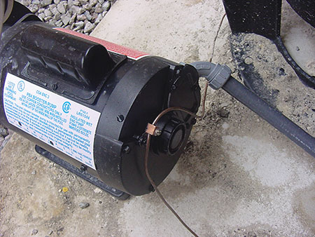
- Metal parts of electric equipment associated with the pool water circulating system, including pump motors and metal parts of equipment associated with pool covers, including electric motors. It should be noted that metal parts of listed equipment incorporating an approved system of double insulation, such as a double-insulated pool pump motor, are prohibited from being bonded to the equipotential bonding grid.
- Metal-sheathed cables and raceways, metal piping, and all fixed metal parts that are within 1.5 m (5 ft) horizontally of the inside walls of the pool, and within 3.0 m (12 ft) above the maximum water level of the pool, or any observation stands, towers or platforms, or from any diving structures, that are not separated from the pool by a permanent barrier.
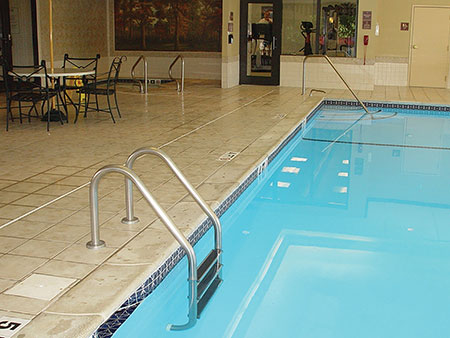
- The pool water itself must also be bonded. An intentional bond of a minimum conductive surface area of 5800 mm2 (9 in.2) is required to be in direct contact with the pool water. This bonding can be accomplished with any of the conductive parts that are required to be bonded as described above. This could include such things as a metal pool ladder or railing where at least 9 square inches of the ladder is in contact with the water. A metal forming shell of a wet-niche luminaire can also satisfy this bonding requirement [see NEC26(C) and photo 1].
For pool water heaters rated at more than 50 amperes and having specific instructions regarding bonding and grounding: only those parts designated to be bonded are required to be bonded; and only those parts designated to be grounded are required to be grounded. As stated previously, accessible metal parts of listed equipment incorporating an approved system of double insulation and providing a means for grounding internal nonaccessible, non−current-carrying metal parts are not permitted to be bonded by direct connection to the bonding grid. The equipment grounding conductor run with the supply branch circuit conductors to the motor is the permitted means used to ground the internal nonaccessible metal parts of these double-insulated motors.
Where a double-insulated water pump is installed, a bonding connection to the equipotential bonding grid is not permitted. However, the Code does require the installation of an 8 AWG solid copper bonding conductor that is of sufficient length to make a bonding connection to a future replacement motor. This requirement is in the event that the replacement motor is not a double-insulated type motor. The bonding conductor is to be extended from the equipotential bonding grid to an accessible location near the motor. Where there is no connection between the bonding grid and the equipment grounding conductor for the premises, this bonding conductor is required to be connected to the equipment-grounding conductor of the pump motor circuit. This connection could be made at the motor termination compartment or in a suitable junction box or other enclosure [see NEC 680.26(B)(6)].
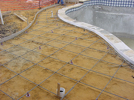
Equipotential Bonding Grid
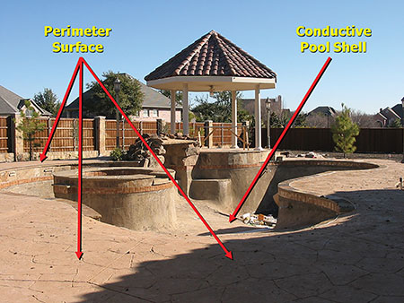
All the metallic structural components and other metal fittings, wiring methods and equipment must be connected together to form an equipotential bonding grid. The equipotential bonding grid is divided into two (2) distinctive parts, the conductive pool shell (belly steel) and the perimeter surfaces (deck steel) (see photo 2). For the conductive pool shell, poured concrete, pneumatically applied or sprayed concrete, and concrete block (including painted or plastered coatings) are all considered conductive materials due to water permeability and porosity. Vinyl liners and fiberglass composite shells are not included in these bonding requirements and are considered nonconductive materials. For the perimeter surfaces, the equipotential bonding grid is to extend under paved walking surfaces for 1 m (3 ft) horizontally beyond the inside walls of the pool unless separated from the pool by a permanent wall or building 1.5 m (5 ft) or more in height. The deck or perimeter surface also includes unpaved surfaces as well as poured concrete and other types of paving and is required to be attached to the pool reinforcing steel or copper conductor grid of the conductive pool shell at a minimum of four (4) points uniformly spaced around the perimeter of the pool. For nonconductive pool shells, bonding at four points is not a requirement. The components and make-up of the conductive pool shell and the perimeter surfaces will be discussed in greater detail later in this article.
The bonding connection between the various components of the equipotential bonding grid can be made with a series of solid copper conductor(s) or with rigid metal conduit of brass or other identified corrosion-resistant metal. If a conductor is used, it may be insulated, covered, or bare, but cannot be smaller than 8 AWG. This bonding conductor is not required to be extended or attached to remote panelboards, service equipment, or any grounding electrodes. This bonding conductor is, again, simply for bonding of metal components together, it is not intended for establishing a connection to earth or a ground-fault return path.
The connection(s) must be made in accordance with NEC 250.8 by such things as listed pressure connectors or clamps that are labeled as suitable for the purpose and are to be made of stainless steel, brass, copper or copper alloy. Where pressure-type connectors are used, be certain they are sized to accommodate the 8 AWG copper bonding conductor and the steel reinforcing bar or whatever is being bonded. Consult the connector manufacturer’s specifications for the proper model connector. Some clamps or connectors are suitable for use with pipe only or with reinforcing rods only. Some of the clamps or connectors are identified for use with a certain size or diameter pipe only, such as ½ in. – 1 in. diameter trade sizes only. This requirement will also ensure a secure connection on what are often widely different sizes of reinforcing bar or rod and the 8 AWG bonding conductor.
If the connection will be covered with concrete or earth, use a wire pressure connector that is identified as being suitable for direct earth burial or concrete encasement, whichever applies.
The process of exothermic welding is an excellent way to bond the required bonding conductor(s) to reinforcing rods or bars. If the exothermic welding process is used, it is critical to use the proper form or mold. A proper form will be sized for both the reinforcing rod and the bonding conductor to be used. Also, be certain all the manufacturer’s instructions are followed. Too “hot” of a load may ruin the connection. Safe work practices and proper personnel protective equipment are required to avoid being seriously burned.
Equipotential Bonding Grid — Conductive Pool Shell
The equipotential bonding grid is comprised of two (2) different and distinct parts. The first of these two that we will discuss is the conductive pool shell. This conductive pool shell is sometimes referred to as the belly steel. The conductive pool shell is to be comprised of the following elements:
Unencapsulated structural reinforcing steel of a conductive pool, where the reinforcing steel is bonded together by the usual steel tie wires or the equivalent. If the structural reinforcing steel is encapsulated in a nonconductive compound or if unencapsulated structural reinforcing steel is not available or utilized at a conductive pool shell, a “copper conductor grid system” is the only Code-compliant alternative and is required to be installed [see NEC 680.26(B)(1)(a) and (b)].
If installed, this copper conductor grid system is to be comprised of (1) through (4) below:
- Constructed of a minimum 8 AWG bare solid copper conductor(s) bonded to each other at all points of crossing (see NEC 250.8 for bonding connection provisions).
- Copper conductor grid system must conform to the contour of the inground pool shell.
- Must be arranged in a 300 mm (12 in.) by 300 mm (12 in.) network of conductors, uniformly spaced in a perpendicular grid pattern with a tolerance of 100 mm (4 in.).
- Must be secured within or under the pool structure no more than 150 mm (6 in.) from the outer contour of the pool shell.
Equipotential Bonding Grid — Perimeter Surfaces
The second element of the equipotential bonding grid is the perimeter surfaces or deck steel as it is sometimes referred to [see NEC 680.26(B)(2)(a) and (b)]. The perimeter surfaces are comprised of the following elements.
Unencapsulated structural reinforcing steel, which for the perimeter surface can consist of such things as structural metal rebar or welded wire mesh. Where structural reinforcing steel is encapsulated in a nonconductive compound or where unencapsulated structural reinforcing steel is not available or utilized, an “alternative means” consisting of copper conductor(s) would then be required to meet the following requirements:
- At least one bare solid copper conductor installed sized at a minimum 8 AWG.
- The conductor(s) are required to follow the contour of the perimeter surface (deck steel).These alternative conductor(s) must also meet the following:
- Permitted to be spliced but only utilizing listed splices or splice kits.
- Installed 450 (18 in.) to 600 mm (24 in.) from the inside walls of the pool.
- Secured within or under the perimeter surface 100 mm (4 in.) to 150 mm (6 in.) below the subgrade.
For the equipotential bonding grid, a clear distinction must be drawn, and attention needs to be directed to the difference between the copper conductor grid system as an alternative for the conductive pool shell and the copper conductor(s) alternate means for the perimeter surfaces. This difference is the reason the Code separates these two distinctive and separate components of the equipotential bonding grid system. Each has separate requirements to achieve the same goal (bonding for the same voltage potential).
There is no Code requirement calling for this bonding conductor(s) to be installed “in one continuous length without a splice or joint.” This would be true if this conductor were a grounding electrode conductor [see 250.64(C)], but this conductor is not a grounding electrode conductor (used for grounding), it is a bonding jumper (used for equipotential bonding). Over the years, I have witnessed numerous installers and inspectors alike requiring this bonding jumper to be installed “in one continuous length without a splice or joint,” which is laborious and unnecessary. The same equipotential bonding can be achieved with a series of multiple short bonding jumpers from such things as ladders, diving boards, metal fences, etc., to the structural metal rebar that often makes up the conductive pool shell (belly steel) and the perimeter surface (deck steel) (see figure 2).
Conclusion
It should be clearly understood that if used, the 8 AWG or larger solid copper bonding conductor used for the “alternative means” for the perimeter surface equipotential bonding is not required to be extended, or attached to any remote panelboard, service equipment, or any grounding electrode. The sole purpose of this bonding conductor is to eliminate any voltage gradients or differences in voltage potential in and around the pool area. The purpose here is not to “ground” the pool structure. How much more grounded can you get than this huge concrete-and-metal structure buried in the earth containing thousands of pounds of water pushing it into contact with the earth even more?
Remember, it is like a marriage: our goal is to bond (marry) conductive components together. Let’s just hope no one gets “grounded” in the process!