NEC AND FIELD PROBLEM
Prior to the 1999 edition of the National Electrical Code, Section 250-24(a), Two or More Buildings or Structures Supplied from a Common Service, basically required a feeder from the first building to be treated as service-entrance conductors at the second building. The neutral conductor was required to be bonded to the building disconnect enclosure and grounded to a grounding electrode no matter what type of wiring method was used.
When installed this way, any metal piping common to both buildings and bonded into the grounding system of both buildings became a parallel path and would carry a large percentage of the neutral current under normal operating conditions. If someone got in series with these paths they could possibly be seriously shocked or electrocuted.
NEC Correction
We published articles addressing and substantiating this problem.1 The results of those articles brought about code change proposals, which reversed the Code requirements. With the 1999 edition, the NEC no longer requires one to reground the neutral conductor at the second building. Now, the main requirement is to isolate the neutral at the second building; only under limited conditions can you reground it.
NEC Current Requirements
Let’s review how to properly install a subpanel. All examples and illustrated wiring methods are for a 120/240-volt, three-wire, single-phase system, unless otherwise noted. All code references are to the 2002 NEC. Unfortunately, some states, such as California, are still using older editions of the NEC; therefore, we have provided Table 1 for a cross reference of code sections referred to in this article. Figures 1, 2 and 3 illustrate the requirements found in Section 250.32, Two or More Buildings or Structures Supplied From a Common Service.
A separate building or structure supplied by a single branch circuit
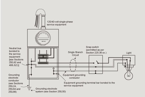
Figure 1. Separate building or structure supplied by a single-branch circuit
Section 250.32(A) starts by requiring a grounding electrode at the separate building or structure. The exception that immediately follows exempts separate buildings or structures that are supplied by a single branch circuit. Figure 1 illustrates that exception. The following are key points for this installation:
1. A grounding electrode at the separate building or structure is not required.
2. Only one branch circuit supplies the separate building or structure.
3. The branch circuit includes an equipment grounding conductor for bonding water and gas pipes [see Sections 250.104(A)(3) and (B)] and for bonding the conductive non-current-carrying parts of all equipment.
4. A disconnecting means is required at the separate building or structure (see Section 225.32 for orderly shutdown, lighting standards and pole sign exceptions). The disconnecting means must be suitable for use as service equipment. However, figure 1 shows the exception to this requirement, which would allow a snap switch as the disconnecting means for garages and outbuildings on residential properties (see Section 225.36 Exception).
Subpanel located in or on a building or structure separate from the service equipment
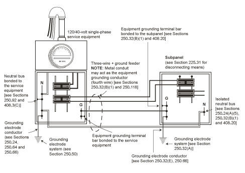
Figure 2. Subpanel located in or on a separate building or structure supplied by a three-wire plus ground feeder
Section 250.32(B), Grounded Systems, contains provisions which result in two different ways to connect grounding and bonding conductors at a subpanel located in or on a building or structure supplied from a separate building or structure. Figure 2 illustrates 250.32(B)(1), the first way to wire a subpanel. The following are key points for this installation:
1. The subpanel is located in or on a building or structure supplied from a separate building or structure.
2. The subpanel is supplied by a three-wire plus ground feeder (two ungrounded (hot) conductors, one grounded [neutral] conductor and one equipment grounding conductor).
3. The neutral bus is isolated from the subpanel by insulating material.
4. A grounding electrode is required. Existing electrodes must be bonded to the equipment grounding terminal bar by a grounding electrode conductor sized according to Table 250.66 and based on the largest ungrounded (hot) conductor of the feeder (note the change from the 1999 NEC, where Table 250-122 was referenced).
5. Water and gas pipes are also required to be bonded to the equipment grounding terminal bar. See Sections 250-104(A)(3) and (B) for the bonding conductor size.
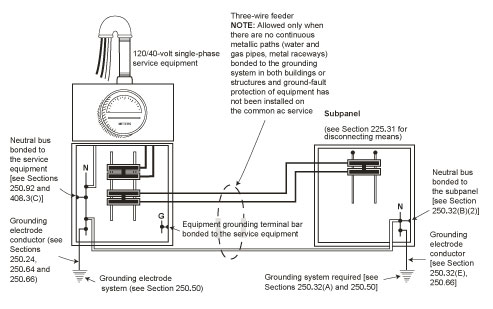
Figure 3. Subpanel located in or on a separate building or structure supplied by a three-wire feeder
Figure 3 illustrates the second way to wire a subpanel. The following are key points for this installation:
1. The subpanel is located in or on a building or structure supplied from a separate building or structure.
2. The subpanel is supplied by a three-wire feeder (two ungrounded [hot] conductors and one grounded [neutral] conductor). An equipment grounding conductor is not run with the feeder.
3. There are no continuous metallic paths bonded to the grounding system in both buildings or structures involved (no parallel neutral paths, i.e., water pipes, gas pipes, metal raceways, and so forth).
4. Ground-fault protection of equipment has not been installed on the common AC service.
5. The neutral bus is bonded to the subpanel equipment grounding bus and enclosure (like the service equipment) and to the grounding electrode(s) and shall be used for grounding or bonding of equipment, structures, or frames required to be grounded or bonded.
6. A grounding electrode system is required (just as it is for the service equipment), and the grounding electrode is connected to the neutral bus by a grounding electrode conductor sized according to Table 250.66 and based on the largest ungrounded (hot) conductor of the feeder. (Again, note the change from the 1999 NEC, where Table 250-122 was referenced.)
7. Water and gas pipes are required to be bonded to the neutral bus. See Sections 250.104(A)(3) and (B) for the bonding conductor size.
Parallel neutral paths for current may also exist from subpanels incorrectly installed in or on the same building or structure as the service equipment. Let’s also review how to install these panels.
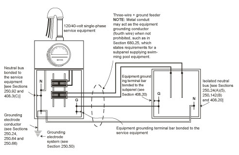
Figure 4. Subpanel is located in or on the same building or structure as the service equipment and is supplied by a three-wire plus ground feeder
Subpanel located in or on the same building or structure as the service equipment.
Sections 250.24(A)(5) and 408.20 limit the installation of subpanels to one method when the panel is located in or on the same building or structure as the service equipment. Figure 4 illustrates the only grounding and bonding connections allowed in this situation. Remember the following key points for this installation:
1. The subpanel is located in or on the same building or structure as the service equipment.
2. The subpanel is supplied by a three-wire plus ground feeder (two hots, one neutral and one equipment grounding conductor). Metal conduit may act as the equipment grounding conductor when not prohibited, such as in Section 680.25, which contains requirements for a subpanel supplying swimming pool equipment.
3. The neutral bus is isolated from the subpanel by insulating material (plastic, and so forth).
4. No electrode is required at the subpanel location.
FIELD CORRECTIONS
Recommendations to eliminate parallel neutral paths and to correct improperly installed subpanels
Thousands of existing subpanel installations have the problem of parallel neutral paths. We have come full circle with this problem (first by addressing the Code problem and now the field problem). We will now try to solve the issue of what to do with these existing installations. Remember, all corrective measures must first be approved by the authority having jurisdiction (local electrical inspector) in your area before you start.
The first existing installation is as follows:
Existing Field Conditions
1. The subpanel is located in a separate building.
2. The subpanel is supplied by a three-wire plus ground feeder (two hots, one neutral and one equipment grounding conductor).
3. The subpanel has a neutral bus that can be isolated.
4. The neutral conductors, the equipment grounding conductors and the subpanel’s grounding electrode conductor all terminate on the neutral bus, which is bonded (by a screw or strap) to the panel enclosure.
5. The feeder raceway is metal.
6. The water and gas pipes are not bonded.
Field Problems
This existing installation does not meet the requirements of Section 250.32 for the following reasons:
1. The feeder’s metal raceway, equipment grounding conductor and the subpanel’s grounding electrode are all parallel neutral paths that need to be eliminated.
2. The water and gas pipes are not connected to the electrical supply in a manner that establishes an effective ground-fault current path.
Recommended Corrections
1. Turn off the power to the subpanel.
2. Disconnect the bonding screw or strap that bonds the neutral bus to the subpanel enclosure. The neutral bus is now isolated from the subpanel enclosure.
3. Remove all equipment grounding conductors and the grounding electrode conductor from the neutral bus. Only grounded (neutral) conductors are to remain connected to the neutral bus.
4. Install an equipment grounding terminal bar (see the panel’s label or installation instructions for the recommended type of grounding bar and its mounting instructions). When installed correctly, this grounding bar will be attached (bonded) directly to the subpanel’s enclosure.
5. The water and gas pipes are required to be bonded to the equipment grounding terminal bar. See Sections 250.104(A)(3) and (B) for the bonding conductor size.
6. All equipment grounding conductors and the grounding electrode conductor are required to be connected to the equipment grounding terminal bar.
7. Turn the subpanel’s power back on.
Problem Solved
The parallel neutral current paths have been eliminated from the metal raceway, equipment grounding conductor and the grounding electrode. The water and gas pipes are bonded back to the electrical supply and now have an effective ground-fault current path that will facilitate the operation of the overcurrent device should a ground fault to the piping occur.
Our second existing installation is as follows:
Existing Field Conditions
1. The subpanel is located in a separate building.
2. The subpanel is supplied by a three-wire feeder ( two hots and one neutral).
3. There are continuous metallic paths (water and gas pipes) bonded to the neutral bus in both buildings or structures involved.
4. Ground-fault protection of equipment has not been installed on the common AC service.
5. The neutral bus is bonded to the subpanel enclosure (by a screw or strap) and is also acting as the equipment grounding terminal bar.
6. There are no grounding electrodes connected to the subpanel.
7. The subpanel feeder is in PVC electrical conduit.
Field Problems
1. The water and gas pipes are parallel neutral paths.
2. There is no grounding electrode connected to the subpanel.
Recommended Corrections
1. Turn off the service power.
2. Pull an equipment grounding conductor with the subpanel’s feeder.
3. Disconnect the bonding screw or strap that bonds the neutral bus to the subpanel enclosure. The neutral bus is now isolated from the subpanel enclosure. Disconnect all equipment grounding and bonding conductors.
4. Install an equipment grounding terminal bar and connect all equipment grounding conductors to it.
5. Install a ground rod and connect it with a grounding electrode conductor to the equipment grounding terminal bar.
6. The water and gas pipes are to be bonded to the equipment grounding terminal bar. See Sections 250.104(A)(3) and (B) for the bonding conductor size.
7. Turn on the service power.
Problem Solved
The parallel neutral current paths have been eliminated from the water and gas pipes. The equipment grounding and bonding conductors have been removed from the neutral bus and attached to an equipment grounding terminal bar, along with the ground rod via the grounding electrode conductor. The neutral bus has been isolated from the subpanel enclosure.
Our last existing installation involving a subpanel is as follows:
Existing Field Condition
1. The subpanel is located in the same building as the service equipment.
2. The subpanel is supplied by a three-wire feeder in flexible metal (steel) conduit, over 1.8 m (6 ft) long and not listed for grounding.
3. There is no equipment grounding conductor with the feeder supplying the subpanel.
4. There is no equipment grounding terminal bar, grounded conductors (neutrals) and equipment grounding conductors are all connected to the neutral bus, which is bonded to the subpanel enclosure.
Recommended Corrections
1. Turn the service power off.
2. Pull an equipment grounding conductor with the feeder supplying the subpanel.
3. Disconnect the bonding screw or strap that bonds the neutral bus to the subpanel enclosure. The neutral bus is now isolated from the subpanel enclosure. Remove all equipment grounding conductors.
4. Install an equipment grounding terminal bar and connect all equipment grounding conductors to it.
5. Turn on the service power.
Problem Solved
The parallel neutral current path has been eliminated from the flexible metal conduit. The equipment grounding and bonding conductors have been removed from the neutral bus and attached to an equipment grounding terminal bar along with the new equipment grounding conductor pulled with the feeders. The neutral bus has been isolated from the subpanel enclosure.
OTHER PARALLEL NEUTRAL PATHS
Our focus on neutral current on multiple paths has primarily been between services and subpanels. However, objectionable current on the grounding and bonding paths and other metal parts may be created from other improper connections between neutral and ground or grounded metal enclosures. We will now discuss two common situations where parallel paths for normal neutral current are also created.
Non-Separately Derived Systems—Transformers and Generators
Our first example will cover non-separately derived systems such as an emergency or standby generator. On non-separately derived grounded systems (example: a 480Y/277V system with a three-pole transfer switch where the neutral is carried through solid) common installation errors, code violations and various grounding schemes can create parallel paths for neutral currents over grounding and bonding paths. This would be in violation of Section 250.6, Objectionable Current Over Grounding Conductors.
Parallel Neutral Paths
Many times generators are shipped from factories with their neutrals bonded to their case. If the generator is connected through a transfer switch which does not open the service supplied system neutral (as in the example above), the generator’s ground and neutral conductors, which are bonded together at the generator, will establish parallel neutral paths through the grounding conductor, interconnecting metal raceway and the generator’s electrode.
Recommended Corrections
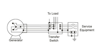
Figure 5. Grounding a non-separately derived AC generator system
The recommended correction in this case would be to isolate the neutral at the generator from the case, grounding conductors and electrodes. The neutral is also isolated from the transfer switch enclosure; however, it is bonded to the service equipment enclosure, in addition to being grounded there (see figure 5).
Separately Derived Systems—Transformers and Generators
Our second example will cover separately derived grounded systems which include transformers and generators. In the case of our 480Y/277V system used above, it is now connected through a four-pole transfer switch where the neutral is switched open. The neutral from the generator and the neutral at the service are now isolated from each other. The neutral is also isolated from the transfer switch enclosure (see figure 6).
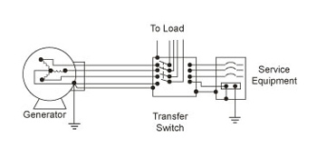
Figure 6. Grounding a separately derived AC generator
Code Requirement To Prevent Parallel Neutral Paths
Requirements for grounding a separately derived AC system are located in Section 250.30. Simply put, this section requires bonding and grounding connections either at the transformer or generator, or at the first (fused) switch or circuit breaker they feed, but not at both (see Section 250.30(A)(1) Exception 1), for that would establish a parallel neutral path on the grounding and bonding paths between them (see figure 7).
CONCLUSION
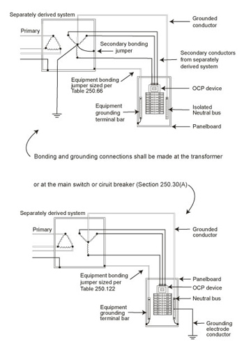
Figure 7. Grounding separately derived transformer system
We have pointed out the problems of neutral current on parallel paths in previously published articles. Those articles helped to change the Code in order to prevent those problems from occurring in new installations. This article illustrates these changes and also tells you how to fix the problems in existing installations.
Now that we have come full circle, so to speak, on the problems of parallel neutral paths, where do we go from here? Well, here’s a tangent to consider:
TANGENT
We do not think we can tell people too often that they should study the Code, in general, and Article 250, in particular. Article 250 has undergone significant revision in both the 1999 and 2002 editions of the NEC. The intent of these changes was to make the article easier to read and understand. The changes to Section 250.32 as illustrated above were only one of many.
One of the more important changes was the addition of Article 250.4 (250-2 in the 1999 edition), which provides performance requirements for grounding and bonding. Performance requirements are helpful since they actually define what grounding and bonding are intended to accomplish in the electrical system.
Article 250 now clearly states that grounding performs a specific function in the electrical system and that bonding performs a separate and distinctly different function. The 1999 NEC introduced the term fault-current path to better describe the necessary function performed by
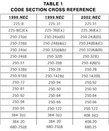
Table 1
bonding. The 2002 NEC adds definitions of ground-fault, ground-fault current path and effective ground-fault current path. These definitions, in conjunction with the performance requirements, help to explain the “why” of grounding and bonding requirements.
Proper grounding and bonding are critical elements in a safe electrical installation. All inspectors and installers are encouraged to review the “new” Article 250 and become familiar with the significant changes. We also recommend IAEI’s Soares Book on Grounding for further study on this important topic.
1 “Subpanels: Special Wiring and Grounding Requirements,” 1993 Sept./Oct. Building Standards Magazine and the Building Official and Code Administrator Magazine, Sept./Oct. 1994; “A Question of Current—Objectionable or Not,” IAEI News, May/June 1996; and a follow-up article by Tom Trainor, “A Question of Current—or Code Interpretation?” IAEI News, Sept./Oct. 1996.)