The division classification method has been used in the United States since being incorporated into NEC 1920 to cover electrical and electronic equipment and wiring in extra-hazardous areas where fire or explosion hazards may exist from flammable and combustible liquids, vapors, or gases. The use of the term extra-hazardous locations implied that an electrical installation was already a hazardous installation but where used in areas, rooms, or compartments with some chemicals, it was more hazardous than usual. In NEC 1931, the term classifications was added to the NEC along with Class I, Class II, and III. The term extra-hazardous has been dropped from the NEC. These areas are now called hazardous (classified) locations which differentiates the hazardous chemical areas with electrical equipment from hazardous health areas.
The NEC 1996 was the first edition to address the new hazardous (classified) method of zone classification. The NEC 1996 identified the newly introduced zone classification method as Class I, Zone 0, 1, and 2 and provided a basis to build upon in subsequent editions of the NEC.
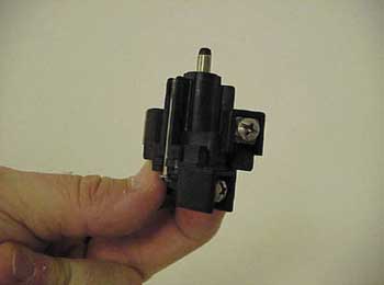
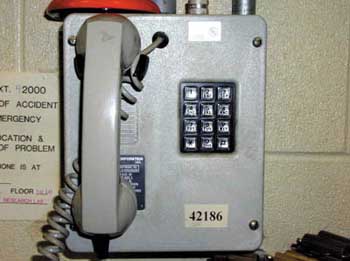
Photo 2. Intrinsic safe telephone
This new method of protection was based primarily upon the international method of zone protection and covered only limited concepts of the international technique. Definitions for this new method of zone protection were provided in a new Article 505 but contained limited information and application techniques. The NEC 1996 tied the division type of hazardous location articles together with the new zone type of protection techniques but the information was rather difficult to find since the new zone protection text was inserted into various places within the general hazardous locations articles. Even though the bulk of the information was in Article 505, it was necessary to extract some of the zone classification information from Articles 500 and 501 primarily covering Class I, Division 1 and 2 hazardous (classified) locations.
In NEC 1999, all references to the zone concept of hazardous (classified) locations were removed from Article 500 for general hazardous location concepts and from most of Article 501 for Class I, Division 1 and 2 installations. A fine print note was left in 500-1 to provide the user with direction to Article 505 containing the bulk of the information on the zone concept of area classification.
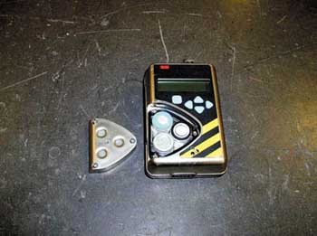
Photo 3. Battery-operated intrinsic safety (IS) gas detector
This single article concept for zone applications provided a more user-friendly method to access pertinent information where applying the zone concept. Article 505 provides information on equipment and wiring methods that are permitted in a Zone 0, Zone 1, and Zone 2 classified area. All other applicable rules would apply to these installations, except as amended by Article 505 or amended by those requirements in Article 504 dealing with intrinsically safe installations.
The zone concept was further enhanced in NEC 2002 by changing the basic layout of Article 505 to fit the new numbering sequence required by the NEC Style Manual. All definitions were moved to 505.2; 505.3 covers other applicable rules located in other articles; and 505.4 provides general information pertaining to zone installations. This was done to provide consistency of section numbering with other similar articles.
Further changes to Article 505 made it completely independent of Articles 500 and 501. Section 505.15 for wiring methods in a zone area was expanded to match its counterpart in 501.4 for wiring methods in a Class I, Division 1 and 2 area. Section 505.16 was inserted to cover the sealing requirements for zone methods rather than just referring back to 501.5 as was done in the previous Codes.
Location and General Requirements for Article 505
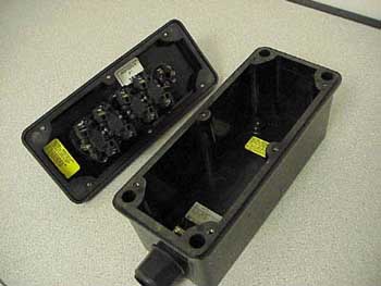
Photo 4. Open view of control station
In zone applications, hazardous locations are classified in accordance with the properties of flammable liquids, gases, or vapors that may be present in the area where electrical equipment is installed. The liquids, gases, or vapors must be likely to form ignitable concentrations and the quantities of the material must be sufficient to pose a hazard when mixed with a sufficient quantity of air. These conditions are similar or often the same as the conditions required for a similar location being designed and installed in the division concept.
Each area should be considered individually in determining the classification and care should be taken to not over-classify, as well as to not under-classify. Electrical equipment should be installed and connected in an area that is outside the hazardous (classified) location; however, where this not possible or practical, then special electrical equipment must be installed in the hazardous (classified) location. All of the factors that are normally associated with division area classification would apply to a zone classification, such as temperature, density or molecular weight of the substance, air circulation, quantity, pressure, and so forth.
Highly oxygenated areas are outside the scope of both the zone classification and the division classification systems. These areas have had the ignition and burning characteristics of materials changed by exceeding the normal volume of oxygen of air that is mixed with the flammable gas or vapor. Where highly oxygenated areas are encountered, the user should refer to the specialized documents that deal with these types of areas and comply with the requirements for installation of electrical equipment in those areas.
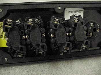
Photo 5. Close up shot of control station
Areas where pyrophoric materials are present or handled are also outside the scope of both the zone classification and the division classification systems. Pyrophoric materials can be ignited just by introducing the material to air. Where these chemicals are used, installation of special electrical equipment is usually not necessary. However, care should be taken since there may be other combustible chemicals in the area that may require special electrical equipment.
Since much of the electrical equipment built for the European and other world markets incorporate metric measurement and sizing, it may be necessary to provide adapters to convert from the standard NPT threads that are used in the United States to the metric threaded entries or fittings provided with the equipment. If equipment with metric threads is provided for use in the United States, the NEC requires that metric to NPT adapters be included with the equipment or be marked to identify the threaded entries as metric threads.
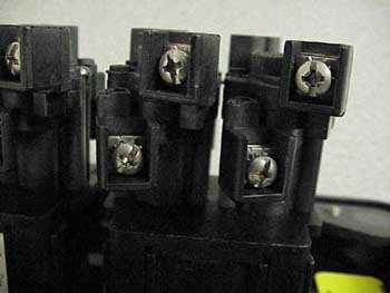
Photo 6. Close up of increased safety equipment terminals
NPT threads provide a ¾ inch per foot taper. Most standard conduit threading equipment available in the United States uses NPT thread. By conforming to a standard threaded system and providing a standard to metric adapter, electrical equipment with metric threads can be readily and safely adapted. Good electrical and mechanical continuity of conduit connections by the proper threaded adaptor to the enclosure can prevent sparking between the fitting, the conduit, and the enclosure during an electrical fault. The proper fitting can also ensure the integrity of the explosionproof or flameproof path by permitting the venting and subsequent cooling of the hot flaming gases after an explosion occurs within the enclosure.
Definitions of Zone Classification
Zone 0 Locations
A Zone 0 location involves ignitable concentrations of flammable gases or vapors that are present continuously or present for long periods of time. This classification includes locations inside tanks in which flammable or combustible liquids, gases, or vapors are stored or locations such as between the inner or outer roof sections of a floating roof tank containing volatile flammable liquids. If venting is provided to allow the gases or vapors to escape from inside the tank during the process of filling, there may be an area outside of the tank near the opening of the vent that is considered to be a Zone 0 location. In some cases, the area around the vent outlet would be considered to be a Class I, Zone 1 location, depending upon the amount of air circulation and the type of material involved.
For Zone 0 locations, it is recommended that electrical equipment be located in an area outside the Zone 0 location. This is not always feasible since measurement equipment and other electrical equipment may be necessary for the function and monitoring of the system. In a Zone 0 location, intrinsically safe apparatus and the associated intrinsically safe circuit are the only wiring methods and protection technique that are permitted to be installed.
Zone 1 Locations
A Zone 1 location, similar to Class I, Division 1 location, is one in which there may be ignitable concentrations during normal operating conditions or ignitable concentrations exist frequently from repair or maintenance of the equipment. A Zone 1 would be a location where equipment breakdown or faulty operation of the equipment could release ignitable concentrations of gases or vapors and simultaneous failure of electrical equipment. Areas that are adjacent to a Class I, Zone 0 location where ignitable concentrations of gases or vapors could migrate are also considered to be Zone 1 locations.
The normal classification for Zone 1 locations does not take into consideration catastrophic leaks. It does, however, consider small leaks from valves, pump packing glands, and other similar leakage considered common for equipment handling hazardous materials.
Zone 2 Locations
A Zone 2 location and a Division 2 location are essentially the same and have similar definitions. It is a location where vapors or gases are not likely to occur during normal operation but if a leak does occur, it would normally be for a short duration of time.
A Zone 2 location is one where the liquids, gases, or vapors are handled, processed, or used in an area but are normally confined within closed piping or containers that can only leak as a result of a rupture or some other abnormal condition.
Positive mechanical ventilation is often used to prevent the buildup of ignitable concentrations of gases or vapors and, thus, to reclassify or declassify the area. Should the ventilation system break down, an ignitable concentration could require classification as a Zone 2 location.
An area that is adjacent to a Class I, Zone 1 location from which ignitable concentrations of flammable gases or vapors could migrate would be a Zone 2 location, unless positive mechanical ventilation has been provided and there are safeguards to ensure against ventilation failure.
Protection Techniques for Zone Locations
Many of the protection techniques for zone locations in the NEC are modeled after the International Electrotechnical Commission (IEC) standards and the International Standards Organization (ISO) standards. These international organizations have been primarily responsible for providing standards on electrical equipment for many countries.
Underwriters Laboratories Inc. (UL) has further adapted these IEC documents with minor changes into a multi-part American National Standards Institute (ANSI) document, ANSI/UL 2279-2001, the Standard for Electrical Equipment for Use in Class I, Zone 0, 1, and 2 Hazardous (Classified) Locations. This UL standard is used for testing and listing of electrical equipment for use in zone classified areas and provides the manufacturer and the user with a detailed description of the particular protection techniques that can be used for these areas.
Section 505.4(B), fine print notes provides standard references for important information involving hazardous locations. Each protection technique permitted in a zone installation is covered in 505.8 and in fine print notes that immediately follow many of these protection techniques.
1. Flameproof (Type “d”) Equipment
Flameproof (Type “d”) is a type of protection that is similar to explosionproof equipment protection that has been one of the most common protection techniques used in the United States. In this protection technique, the equipment is in an enclosure that has been tested to withstand an internal explosion of a gas- or vapor-to-air mixture that can penetrate into the interior of the enclosure. The enclosure must contain the flame and the explosion pressure without damaging the enclosure and without permitting the flame to leave the enclosure through any joints or other openings in the enclosure and without igniting the surrounding gases. [Photo 1]2. Purged and Pressurized (Type “p”) Equipment
Purged and pressurized (Type “p”) is a type of protection that uses inert gas or instrument quality air as a protective gas to purge the inside of the enclosure of any hazardous quantity of flammable gases or vapors. The enclosure is then kept pressurized at a pressure high enough above the outer atmosphere surrounding the enclosure to prevent the flammable gas or vapor from re-entering the enclosure. This guards against an ignitable concentration of gas accumulating within the enclosure and then being ignited by an arcing or sparking part or hot electrical equipment. This protection technique also permits a general type enclosure to be used rather than an explosionproof or flameproof enclosure, as would normally be the case.3. Intrinsic Safety (Types “ia” or “ib”) Equipment
Intrinsic Safety (Types “ia” or “ib”) is a type of protection technique that uses an apparatus that limits the maximum level of current and voltage measured as energy (usually in millijoules) under normal or fault conditions that can be delivered into the hazardous location. The intrinsically safe associated apparatus providing this energy limitation has a further identification marking on the equipment that indicates the type of intrinsic safety. The marking will be “ia” or “ib” and should be located on the nameplate of the apparatus. This equipment should provide a level of safety that, even in a double fault condition (“ia”) or a single fault condition (“ib”), there will not be enough ignition energy to ignite the gas or vapor in that area. [Photo 2 and Photo 3]4. Protection (Type “n”) Equipment
Protection (Type “n”) equipment is a protection technique applied to electrical equipment which does not have enough ignition energy to ignite the gas or vapor during normal operation and is not likely to have a fault that could cause ignition. This type of protection is similar to the nonincendive circuits and equipment used in Class I, Division 2 locations. If there is a possibility of a fault occurring within the system, then some other method of protection should be chosen or extra protection against faults should be incorporated.5. Oil Immersion (Type “o”) Equipment
Oil immersion (Type “o”) equipment is a type of protection in which the electrical equipment is immersed in a protective fluid of nonconductive silicone or mineral oil. The fluid level should be such that the electrical parts and any arcing or sparking parts of the oil-encased equipment are immersed and the liquid always covers the electrical parts. This ensures that the gas or vapor located above the arcing or sparking parts or the gas or vapor located exterior to the enclosure cannot be ignited by the electrical arcing parts within the oil.6. Increased Safety (Type “e”) Equipment
Increased safety (Type “e”) equipment is a type of protection applied to electrical equipment that does not produce arcs or sparks during normal operation and under certain abnormal conditions. This equipment has additional security against the possibility of excessive temperature and the equipment is assembled very carefully to ensure that arcing or sparking from part to part or connection to connection will not occur. The increased safety concept is often combined with flameproof and other protection techniques at the termination point outside of the enclosure to permit a connection point. [Photo 4, Photo 5, Photo 6, and Photo 7]7. Encapsulation (Type “m”) Equipment
Encapsulation (Type “m”) equipment is a type in which any parts that could cause ignition of an explosive atmosphere by either excessive temperature or by arcing or sparking has been encapsulated in a compound of some sort. This encapsulation will prevent the flammable or combustible material from migrating into the enclosure in a large enough volume to form an ignitable atmosphere at the point of excessive temperature or electrical arc within the equipment.8. Powder Filling (Type “q”) Equipment
Similar to encapsulation equipment, powder filling (Type “q”) equipment protection incorporates a quartz or glass powder as a filling material. This method surrounds the hot or arcing electrical parts and doesn’t permit the ignition of the gas or vapor at a point either inside or outside the equipment enclosure.
Special Precaution with Zone Equipment and Area Classification
The proper use and maintenance of zone equipment is as critical as the ability to properly classify the area for the electrical installation for the facility. It is important that all personnel involved in the design, installation, maintenance, and inspection of zone areas be very familiar with the zone concept.
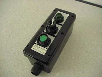
Photo 7. Control station protection method “edm” increased safety enclosure with flameproof switches and encapsulated indicating light
If abnormally low temperatures are encountered at the installation, such as below -20°C (-4°F), special equipment may need to be installed. If these low temperatures are encountered, it should be noted that many liquids are well below their flash points and are no longer a hazardous concentration issue; however, low temperature may also adversely affect the equipment operation, unless the equipment has been designed to operate in extremely low temperatures.
For Class I, Zone 0, 1, and 2 areas, NEC 1996, 1999, and 2002 require classification of areas, selection of equipment, and selection of wiring methods to be handled under the supervision of a qualified, registered professional engineer. The use of a qualified, registered professional engineer for these systems should help ensure a degree of accountability for the installation and will remain a requirement until a significant number of trained personnel familiar with the equipment design and installation are available.
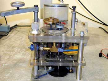
Photo 8. Spark test apparatus for determination of MIC ratio
Care should be taken where an installation that has both division and zone locations exists at the same facility. There may be some applications where the zone system is located adjacent to an existing division area, and this may require different area classification methods for the same plant or facility. This dual classification of a facility is acceptable; however, there are certain cautions that the user must observe. Class I, Zone 0 and Zone 1 locations must not abut or overlap any Class I, Division 1 or 2 locations. It is permissible to have Class I, Division 2 and Class I, Zone 2 areas that are adjacent to each other.
Dual classification permits these two different classification methods with their different wiring methods to exist at a single facility but to provide a clear line of delineation between the two different systems. A user could reclassify a Class I, Division 1 or Division 2 area as a Class I, Zone 0, Zone 1 or Zone 2 area provided all of the reclassified space is classified using a single flammable gas or vapor source.
Grouping and Classification of Areas Based on the Chemicals Used
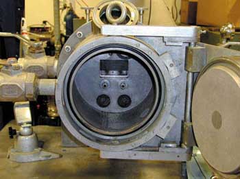
Photo 9. Westerberg apparatus for determining maximum experimental safe gap (MESG)
For the purposes of testing and approval of the electrical equipment suitable for the zone area and to help in area classification of the location itself, air mixtures that have not been oxygen enriched have been classified into three groups. The three group classifications for zone applications are based upon the maximum experimental safe gap (MESG) or the minimum igniting current (MIC) ratio or both. The MIC ratio is based upon the use of methane gas as a base for comparison to the other gases in question. [Photo 8 and Photo 9]
These group classifications are subdivided into Groups IIC, IIB, and IIA according to the nature of the gas or vapor and the type of protection technique. Protection techniques, such as increased safety “e”, encapsulation “m”, purged and pressurized “p”, and powder filled “q” equipment, are not dependent upon the ignition properties of the gases in the group. Their inherent designs will preclude the gases or vapors from entering the enclosures or being ignited by an arcing or hot electrical part.
Group IIC is an atmosphere containing acetylene, hydrogen, or flammable gas, flammable liquid-produced vapor, or combustible liquid-produced vapor mixed with air that may burn or explode when ignited, having either an MESG less than or equal to 0.50 mm or an MIC ratio less than or equal to 0.45.
Group IIB is an atmosphere containing acetaldehyde, ethylene, or flammable gas, flammable liquid-produced vapor, or combustible liquid-produced vapor mixed with air that may burn or explode when ignited, having either an MESG greater than 0.50 mm and less than or equal to 0.90 mm or an MIC ratio greater than 0.45 and less than or equal to 0.80.
Group IIA is an atmosphere containing acetone, ammonia, ethyl alcohol, gasoline, methane, propane, or flammable gas, flammable liquid-produced vapor, or combustible liquid-produced vapor mixed with air that may burn or explode when ignited, having either an MESG greater than 0.90 mm or an MIC ratio greater than 0.80.
Equipment can be listed for the specific gas or vapor, specific mixtures of gases or vapors, or any specific combination of gases or vapors. This permits electrical equipment to be designed, tested, and listed based upon a specific anticipated usage. For example, electrical equipment that has been tested as a Group IIB would normally be required for ethylene-based chemical atmospheres but may also have been tested for hydrogen-based chemicals. This permits the equipment to be marked with a IIB marking instead of having to be subjected to the more rigid tests for acetylene, as would normally be required if a IIC equipment listing is used.
Listing, Marking, and Documentation
Listing of zone equipment is a requirement in 505.20. Equipment listed for use in a Zone 0 location can be used in a Zone 1 or Zone 2 location for the same gas or vapor. Listed Zone 1 equipment can be used in a Zone 2 location for the same gas or vapor. Electrical equipment may be marked with both Division 1 or Division 2 marking and Zone 1 or Zone 2 for the same gas atmosphere. Where marking division equipment for the zone designation, the marking should include the Class I, Zone 1 or Zone 2 designation, the applicable gas classification group, and the temperature class (T Code) of the equipment.
Zone equipment must be marked to indicate the class and the particular zone for which it has been listed. Zone equipment marked for use in the United States will have an “AEx” marking to indicate that the equipment has been listed in accordance with United States nationally recognized testing and listing standards.
Many European and other countries permit manufacturer’s self-certification of electrical equipment for suitability of the equipment for environmental conditions, wire bending spaces, electrical insulation, in other words, the ordinary electrical equipment requirements. These countries do, however, require the equipment used in a zone location be third party certified for the hazardous location into which the equipment will be installed. The “AEx” mark and the testing lab mark should indicate to all persons involved in the installation that the electrical equipment has been tested and listed by a third party certification organization based on U.S. standards for the particular protection techniques plus the aforementioned ordinary electrical equipment requirements for shock and fire hazards.
Temperature and Classification of Zone Equipment
Electrical equipment used in a zone location must be marked with the operating temperature of the equipment using a reference ambient temperature of 40°C (104°F). This ambient temperature provides a starting point at which to test and as a reference to the operating temperature of the equipment. The temperature class must be marked on the equipment in the form of a “T” code. “T1″ is for equipment operating at equal to or less than 450°C; “T2,” for equal to or less than 300°C; “T3,” for equal to or less than 200°C; “T4,” for equal to or less than 135°C; “T5,” for equal to or less than 100°C; and “T6,” for equal to or less than 85°C. Electrical equipment designed for use in an ambient temperature of between -20°C and +40°C do not require any additional temperature marking, other than the “T” code.
Equipment designed be used in an ambient temperature below -20°C or above +40°C must have the ambient temperature range marked on the equipment. This is necessary since the ambient temperature at which it has been designed may affect the operating temperature of the equipment. These extremely low or high ambient temperatures may also affect the amounts of gases or vapors present. Low temperatures may also produce higher explosion pressures in flameproof or explosionproof equipment.
Equipment suitable for use in an ambient temperature exceeding 40°C (104°F) must be marked with both the maximum ambient temperature in which it may be operated and the operating range of the equipment at that elevated temperature. Extremely high ambient temperatures may elevate the gas or vapor close to the autoignition temperature of the gas or vapor. It is critical that the autoignition temperature of a gas or vapor is not exceeded by contact with extremely hot electrical equipment.
Electrical equipment that is not of the heat producing type or that operates at no greater than 100°C (212°F) is not required to have a marked temperature range or a marked operating temperature. Many hazardous chemicals have a much higher autoignition temperature than 100°C, but even if dealing with a chemical that has a low autoignition temperature, the electrical equipment is just one of many items that could be located in the area and be a concern for causing possible ignition of the material.
Conclusion
By providing the user with an optional method for area classification and an expanded number of equipment options, the NEC has become a more global and progressive document. It has also expanded the ability of manufacturers to enter into the global market in a more competitive way.



Find Us on Socials