Information on various old and new products for lighting and other uses will be provided where these products are being adapted to work within the framework of the NEC for this new technology. Studying the acceptance of this technology for lighting, and then viewing the expansion of the supporting technology with the electrical industry’s rapid implementation of this new low-voltage power concept, coupled with other innovative applications, are key points underscoring the need for this new technology. To spread the understanding of this concept and to provide the user with a complete understanding of this technology, the first step is to provide a brief history of how this technology was developed, profiling the early attempts to have the ceiling grid power distribution technology specifically adopted into the NEC. The second step is to determine where the technology is at the present time inclusive of how the NEC covers low-voltage ceiling grid technology as an important part of the overall construction technology as it currently exists. The third step anticipates where the low-voltage ceiling grid technology is at the present time and will be in the future, covering both lighting and other uses.
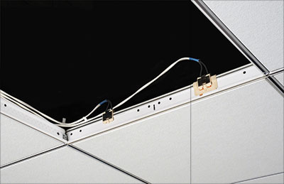
Photo 1. Low-voltage suspended ceiling power distribution system
Historical Background
This new technology was derived by the realization of some people in the electrical industry that supplying permanent power for lights, receptacles, and other equipment in an office area within a building did not permit flexibility or ease of revision, remodeling, or reconstruction within these areas. A segment or coalition of the construction manufacturing community began work on a method of establishing an easier and less expensive method of providing power for general lighting and power loads and task lighting in an office area. The designers and developers of this new technology had to determine what the NEC would permit and then integrate the existing systems into a highly flexible wiring system. Decisions had to be made about the power source to be used, how to distribute power to the equipment, the type of connections to the power source that would be both safe and compliant with the NEC and the overall functional design of the system. In addition, determining the power level for any new system was a major concern since the higher the voltage and amperage for a power system, the less system flexibility.
The NEC provided the technical basis for using low-voltage power for the ceiling grid low-voltage power distribution in Article 725 and similar but related articles. For example, Article 640 covered audio signal processing, amplification, and reproduction equipment (audio and video equipment) and permitted Class 2 and Class 3 low-voltage power and wiring methods in accordance with Article 725. Heating and air-conditioning systems, designed with Classes 2 and 3 low-voltage power systems for heating and air-conditioning controls and thermostats, as well as control of variable air volume (VAV) dampers, rely upon Article 430 for motors, on Article 440 for air-conditioning systems, and on Article 422 for appliances. While Class 2 or 3 power-limited systems are often used for motor controls, as noted by requirements in430.72, Article 725 generally covers remote control, signaling, and power-limited circuits. Therefore, the low-voltage ceiling grid power distribution design coalition determined that Article 725 was the key to providing the power for this low-voltage lighting ceiling grid distribution system.
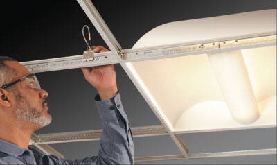
Photo 2. Installation of load connector to grid rail
Class 2 and Class 3 control, signaling, and power-limited circuits are low voltage with low-amperage circuits, or very low amperage with higher-rated voltage circuits that, due to their power limitations, will not normally initiate or start a fire since the energy source is low enough to not provide ignition of most material. Class 3 circuits can be a shock hazard due to their higher ampacity but are not normally a fire hazard; while Class 2 circuits will not provide ignition to most flammable materials and do not have enough energy to provide a shock hazard to personnel in a dry application, especially where the cables, components, and power supply are insulated by at least 150-volt insulation.
There are two different categories for Class 2 and Class 3 circuits with the technical characteristics of the two power-supply categories located in Tables 11(A) and 11(B) within Chapter 9 of the NEC. Table 11(A) covers alternating current (ac) power source limitations, and Table 11(B) covers direct current (dc) power source limitations. Both tables have inherently limited power supplies and not-inherently limited power sources as applied to both Class 2 and Class 3 power sources, with more to be explained on these two issues later. With an inherently limited power source, overcurrent protection is not required. With a not-inherently limited power source, overcurrent protection is required. As can be seen in Tables 11(A) and 11(B), Class 2 circuits have three basic voltage and amperage columns for inherently limited power supplies; and two basic voltage, amperage, and power columns for not-inherently limited power supplies. Class 3 circuits have one voltage, amperage, and power column for inherently limited power supplies, and two for not-inherently limited power sources. There is more emphasis on the Class 2 systems in this article, since Class 2 systems are used to supply power for the low-voltage ceiling grid power distribution systems.
Basics for NEC Coverage — General Requirements
Before covering the requirements for Class 2 and Class 3 remote-control, signaling and power-limited circuits found within Article 725, basic Code arrangement must first be understood. This basic requirement is covered in 90.3 of the NECthat states that the Code is divided into the introduction and nine chapters. The first four chapters cover general electrical requirements [Chapter 1: General electrical requirements; Chapter 2: Wiring and Protection; Chapter 3: Wiring Methods and Materials; and Chapter 4: Equipment for General Use]. Chapters 5, 6, and 7 are specialty chapters dealing with special occupancies, special equipment, or other similar types of special conditions, respectively, involving these special occupancies or equipment. Since these three specialty chapters cover special equipment and occupancies, the general rules and requirements found in the first four chapters can be supplemented or modified by the information found in Chapters 5, 6, and 7. This means that allof the general requirements in Chapters 1 through 4 must be followed unless special equipment, special occupancies, or special conditions require or permit us to deviate from the general rules. Specific requirements for low-voltage circuits covered in Article 725 can add to or amend any requirements for similar circuits found within Chapters 1 through 4. Section 90.3 also permits requirements that are located in Chapter 3 and in Article 725, specifically, to apply to the low-voltage suspended ceiling power distribution wiring system that will be located in new Article 393, covering the installation of low-voltage suspended ceiling power distribution systems as stated in the scope of this new article.
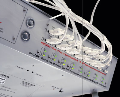
Photo 3. Grid Class 1 power server module
These specialized remote-control, signaling, and power-limited circuits are characterized and identified by usage and by any power limitations that are designed into the circuits. This usage and power limitation is what differentiates these specialized circuits from general power and lighting circuits. For this reason, Article 725 provides an alternative to the requirements for general lighting and power circuits that are covered by Chapters 1 through 4. There are different methods for determining wire sizes for these circuits, special derating factors, overcurrent protection for the circuits, insulation requirements for both the conductors and the equipment used in the circuits, and the wiring methods and materials that are used for the low-voltage circuits.
This concept has been further expanded in other sections of the Code, such that new Section 393.10 states, “Low-voltage suspended ceiling power distribution systems shall be permanently connected and shall be permitted … for listed utilization equipment capable of operation at a maximum of 30 volts ac (42.4 volts peak) or 60 volts dc (24.8 volts peak for dc interrupted at a rate of 10 Hz to 200 Hz) and limited to Class 2 power levels in Chapter 9, Table 11(A) and Table 11(B) for lighting, control, and signaling circuits.” In other words, this section states that these circuits must be limited to Class 2 power levels as detailed in Tables 11(A) and (B) in Chapter 9 and protected based on the table applications as indicated in the table notes. For example, some low-voltage equipment is protected by the inherent impedance of the power supply that precedes the control equipment in the circuit. If a Class 2 transformer has enough impedance in its secondary winding, the inherent impedance will protect the equipment and any conductors located on the secondary side of the transformer. The conductors that are used to supply power to the ceiling grid, and are connectedusing a transformer, are also protected by the impedance-limited transformer secondary. If too much current were to occur within the secondary of the transformer circuit, the windings in the transformer secondary willopen before damage to either the conductors or the components occur, thus providing the inherent protection of the circuit.
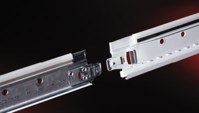
Photo 4. Grid bus rail
The primary of the transformer is still protected by some other means of overcurrent protection, such as fuses or circuit breakers. Section 393.45(A) provides overcurrent protection for the line side of the Class 2 power supply by stating that the listed Class 2 power supply or transformer primary must be protected at not greater than 20 amperes. Section 393.45(B) covers interconnection of power sources by stipulating that listed Class 2 sources must not have the output connections paralleled or otherwise interconnected, unless listed for such interconnection. This will ensure that the Class 2 limitations and protection requirements are maintained without fear of jeopardizing the safety of the circuit. In addition, 393.45(A) permits suspended ceiling low-voltage power distribution systems to have reverse polarity (backfeed) protection of dc circuits by either (1) if the power supply is provided as part of the system, the power supply is provided with reverse polarity (backfeed) protection; or (2) if the power supply is not provided as part of the system, reverse polarity or backfeed protection is provided as part of the grid rail busbar or as a part of the power feed connector.
New Article 393 incorporates quite a few new definitions that are unique to low-voltage suspended ceiling power distributions systems. For example, low-voltage suspended ceiling power distribution system “serves as a support for a finished ceiling surface and consists of a busbar and busbar support system to distribute power to utilization equipment supplied by a Class 2 power supply.” Busbar support is “an insulator that runs the length of a section of suspended ceiling bus rail that serves to support and isolate the busbars from the suspended grid rail”; whereas, a grid bus rail is “a combination of the busbar, busbar support, and the structural suspended ceiling grid system.” A general term for connectorwas provided as “an electromechanical fitting,” but a load connector is “an electromechanical connector used for power from the busbar to” whatever utilization equipment is connected to the busbar. A pendant connector is “an electromechanical or mechanical connector used to suspend low-voltage luminaire or utilization equipment below the grid rail and to supply power from the busbar to utilization equipment.” A power feed connector is “an electromechanical connector used to connect the power supply to a power distribution cable, to connect directly to the busbar, or from a power distribution cable to the busbar.” A rail-to-rail connector is “an electromechanical connector used to interconnect busbars from one ceiling grid rail to another grid rail.” A rail is “the structural support for the suspended ceiling system typically forming the ceiling grid supporting the ceiling tile and listed utilization equipment, such as sensors, actuators, A/V devices, and low-voltage luminaires and similar electrical equipment.” Finally,reversepolarity protection (backfeed protection) is a “system that prevents two interconnected power supplies, connected positive to negative, from passing current from one power source into a second power source.”
Based on 393.57, connections for busbar grid rails, cables, and conductors must be made with listed insulating devices, and these connections must be accessible after installation. Where connections are made in a wall or a concealed location, these connections must be installed in an enclosure in accordance with Parts I, II, and III of Article 314, as applicable. Induction of current into metal conduit or metal enclosures is covered in 300.20; and thesealing of penetrations into hollow spaces, vertical shafts, through walls, ceilings, partitions, and floors or into ventilation or air-handling ducts is still required by Section 300.21. Sections 300.22(B) and (C) detail the requirements for the installation of wiring in fabricated ducts or other spaces used for environmental air. Grounding of the supply side of a Class 2 power source is covered in 393.60(A) by requiring the supply side of the Class 2 power source to be connected to an equipment grounding conductor in accordance with the applicable requirements in Part IV of Article 250. However, the load side of the Class 2 power source does not permit the Class 2 load-side circuits for suspended ceiling low-voltage power grid distribution systems to be grounded at all. This ungrounded low-voltage system helps ensure safety similar to other low-voltage systems not grounded as indicated in 250.22.
The construction specifications for low-voltage suspended ceiling power distribution systems are provided in 393.104 covering sizes and types of conductors. On the load side, 393.104(A) states that current-carrying conductors for load-side utilization equipment shall be copper and shall be 18 AWG minimum. There is also an exception dealing with the size of conductors that states conductors of a size smaller than 18 AWG but not smaller than 24 AWG shall be permitted to be used for Class 2 circuits. Where used, these conductors shall be installed in a Chapter 3 wiring method, totally enclosed, shall not be subject to movement or strain, and shall comply with the ampacity requirements in Table 522.22. In 393.104(B), the power feed bus rail can be 16 AWG minimum or equivalent. For a busbar with a circular cross section, the diameter shall be at least 0.051 in. (1.29 mm) minimum; and for other than circular busbars, the area must be at least a 0.002 in.2 (1.32 mm2) minimum.
Low-Voltage Ceiling Grid Technology — Now and in the Future
This article has provided the technical information and background for suspended ceiling grid low-voltage lighting systems, as well as a glimpse into the future about the technical aspects of a low-voltage suspended ceiling grid power distribution system to supply countless other devices in many different aspects of daily living within an office environment. Some of this new technology is already available on the market; some is being developed as this article is being written, and new technology related to the suspended ceiling grid power distribution may yet be developed. The low-voltage grid system can supply low voltage to luminaires, in-wall audio video systems, office furniture, and under-floor as well as under-carpet distribution and equipment. Security systems and occupancy sensors can be powered by these distribution buses. Ceiling tile-type speakers have already been developed so music and other communication can be piggybacked onto the dc supply on the grid and then tapped to provide for easy surround sound for audio applications. With the advent of new solar photovoltaic technology, window panels with future technology solar photocell coatings could provide direct power to the suspended ceiling grids. Building management control systems for lighting, heating, cooling and all other aspects of building functions can be controlled using a suspended ceiling grid distribution connection to the building energy management system. Fire alarm hard-wired devices could be installed to a permanent source of dc supply with location and connection made just as conveniently and as easily accomplished as the installation of wireless fire alarm devices.
To address the advent of this new technology, UL has published ANSI/UL 2577 Standard for Safety for Suspended Ceiling Grid Low Voltage Systems and Equipment and certifies (Lists) this type of equipment under two product categories that cover the systems as well as the luminaires, connectors, power units and other accessories. These product categories are Suspended- Ceiling-Grid Low-Voltage Lighting Systems (IFFA) and Suspended-Ceiling-Grid Low-Voltage Lighting System Accessories (IFFC) located on page 192 and 193 respectively of the 2013 UL White Book. This is also available online at www.ul.com/database by entering IFFA or IFFC at the category code search field.
As technology changes, the construction and commercial office industry, as well as the various codes and standards affecting the construction of offices, have reacted to provide a safe and reliable method for the appropriate flexibility of power for lighting, sensors, temperature control, and other functional aspects of an office. The low-voltage grid distribution system is a very viable and important part of this flexible power distribution system.
References
1National Electrical Code (NEC) 2014 Edition