The first change that will be apparent is the relocation of Article 80, covering administration and enforcement requirements, to Annex G. The information has not been revised, is still informational in nature as it was in the 2002 NEC, and can be adopted as requirements by jurisdictions that so choose.
A few changes were implemented as the result of ongoing efforts to make the Code more user-friendly. One such revision was the reorganization and renumbering of Article 220. Various similar articles were revised into consistent numbering sequences where possible. To provide more details and understandability for users, the term listed for the purpose was addressed where it appeared within any requirement by identifying the specific purpose. In several of the locations where this term is used, the purpose is evident by the details within rule; however, there are some occasions where the term is used within a requirement that needed the purpose explained. In many cases, this term was reduced from listed for the purpose to just listed.
A few new definitions were added for this cycle. Three of the more significant ones are: system bonding jumper, grounding electrode and coordination, selective. The definition of device has been revised to help clarify requirements where that word is used.
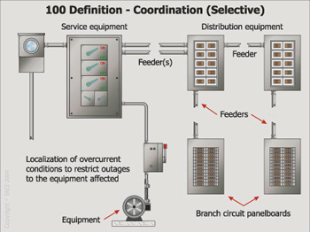
Photo 4
The requirements for arc-fault circuit interrupters and ground-fault circuit interrupters have been revised and expanded in some cases. Rules covering GFCI requirements for commercial and institutional kitchens have been expanded and clarified. A revision within Article 760 prohibits the source circuit for a fire alarm system from being supplied through arc-fault circuit interrupters in addition to ground-fault circuit interrupters. This should provide much needed clarification. GFCI requirements have also been expanded to cover vending machines and receptacles in areas accessible to the public.
There were several revisions in Article 250 relating to grounding and bonding, from the change in the title of the article to the requirements for grounding electrodes. The term effectively grounded has been addressed under a few of the revisions, as well as the reorganization and numbering of Section 250.30(A) covering grounding requirements for separately derived systems.
A few new articles were added. Article 353 has been incorporated into chapter 3 and provides information and requirements for high density polyethylene conduit, Type HDPE. Article 409 provides information needed for industrial control panels. Article 506 provides the requirements for the Zone classification system as an alternative to the division classification system in Articles 500, 502 and 503 for electrical and electronic equipment and wiring for all voltages in Zone 20, Zone 21, and Zone 22 classified locations. Article 682 provides general requirements for electrical installations within and adjacent to natural or artificially made bodies of water.
Fuel cell technology continues to make advances and now is recognized in Articles 700 and 701 as a source for the standby systems covered by those articles. Several revisions to the limited energy articles in chapters 7 and 8 include mainly renumbering and the introduction of a new type of limited energy cable that provides circuit integrity to meet the requirements of survivability during fire conditions for a defined period of time. This type of cable is addressed in the various articles as circuit integrity (CI) cable and is incorporated into Articles 725, 760, and 800.
This preview provides a glimpse of a few of the many changes published in the Analysis of Changes 2005 NEC.
Guest room | Guest suite |
110.12

Photo 1
Mechanical Execution of Work, FPN
Section 110.12 requires electrical equipment to be installed in a neat and workmanlike manner. That term is undefined and has varying interpretations on such things as how plumb and square an enclosure is required to be when mounted, or how level horizontal runs of raceways must be in order to be neat and workmanlike. A fine print note reference to another document is for information only and the provisions included in that publication are not required to be followed by the Code. The FPN refers to ANSI/NECA 1-2000 as describing

Photo 2
accepted industry practices. The basic document that became ANSI/NECA 1-2000 has been used for many years as a guide to help installers and other people in the electrical industry have a better idea of how electrical equipment should look as the result of trained people performing the work. While it is not enforceable and not all industry people agree with every recommendation in the book, it is a beneficial document to better understand what constitutes a neat and workmanlike manner.
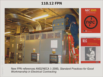
Photo 5
210.5(C)
Ungrounded Conductors
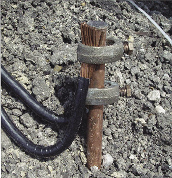
Photo 3
Former 210.4(D) addressed the identification of multiwire branch circuits where more than one nominal voltage system exists in the same building. The text was deleted as the title of 210.4 includes only multiwire branch circuits and the issue raised in Proposal 2-30 concerns the identification of more than just multiwire branch circuits where more than one voltage system supplies the premises. It is as important for the ungrounded conductors of two-wire branch circuits to be identified where those conditions exist as it is for multiwire circuits. The title of 210.5 is “”Identification of Branch Circuits”” and is more appropriate for rules covering the identification of ungrounded conductors in those types of circuits.
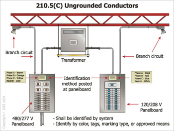
Photo 6
The method of identifying the ungrounded circuits remains the same but the location where the identification is to be made has been further clarified to indicate that the distribution equipment is that where branch circuits are located and not distribution equipment in general. Accepted safety practices include verifying the characteristics of a circuit before working on it and not relying on a marking as the sole indicator of the voltage or system associated with the circuit. While those precautions need to be taken, a properly installed and maintained system should include specific identification of ungrounded branch-circuit conductors where two voltage systems exist in order to initially alert qualified personnel as to the voltage system at that location.
210.12(B)
Dwelling Unit Bedrooms
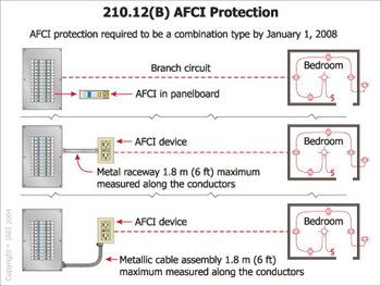
Photo 7
This change requires all arc-fault circuit interrupters installed after January 1, 2008, to be of the combination type. A combination type AFCI provides protection for both series and parallel arc faults. A branch/feeder AFCI, referred to in the new wording in the second sentence of 210.12(B), is presently used to provide protection for the branch circuit. It will continue to be recognized as meeting the requirements of 210.12 until January 1, 2008, at which time only combination type units must be used. The technology needed to design and produce AFCIs that protect against both series arc faults and parallel arc faults is currently available but AFCIs commonly used to comply with 210.12 are not of the combination type. The delayed effective date provides time for combination AFCIs to be designed, produced, and field tested, but also alerts the industry that it must address the issue within that time frame.
The exception was added to provide alternate means of accomplishing the desired protection. It is important to note that a metallic raceway or metallic-sheathed cable must be used and within 1.8 m (6 ft.) of the panelboard as part of this exception requirements.
230.2(A)(6)
Special Conditions
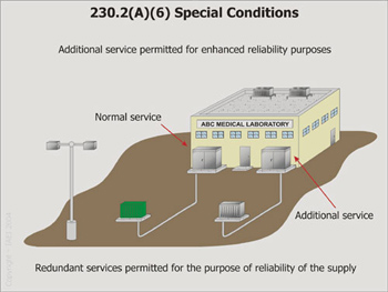
Photo 8
This change to permit an additional service to a building is similar to the one made by including a new 225.6(A)(6) which permits an additional feeder or branch circuit to supply a building for reliability purposes. Previous rules in 230.2 do not specifically include an additional service for this purpose but do permit additional services for fire pumps, emergency systems, legally required standby systems, optional standby systems and parallel power production systems. The new 230.2(A)(6) adds wording to permit another service to enhance reliability but does not require the need for reliability to be based on any specific need. Facilities that can be severely impacted by the failure of or loss of power from a service, such as laboratories or others that perform critical operations, are candidates for using this new provision.
230.82(3)
Equipment Connected to the Supply Side of Service Disconnect
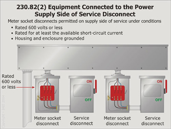
Photo 9
Item (2) in 230.82 previously included meter disconnect switches in the same rule permitting meters and meter sockets to be connected on the supply side of a service disconnecting means. The two conditions associated with that authorized use are that their nominal rating not exceed 600 volts and that all metal housings and service enclosures are grounded. The wording “”meter disconnect switches”” was deleted from item (2) and added in a new item (3) that permits meter disconnect switches to be connected ahead of service disconnecting means but requires that those switches have a short-circuit rating equal to or greater than the available short-circuit current and that all metal housings and service enclosures be grounded. The new language addresses expressed concerns regarding this type of switch being connected ahead of service overcurrent protective devices. It appears that utility personnel have a greater use for meter disconnect switches than others within the industry because it can be used to disconnect power before a watt-hour meter is installed or removed. However, panel actions do not detail the intended use of those switches nor make any determination as to who is authorized to operate them.
240.86(A)
Selected Under Engineering Supervision in Existing Installations
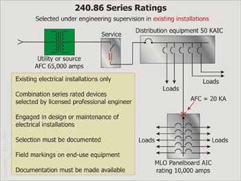
Photo 10
This rule is a new method of determining the combination series rating of overcurrent devices in existing installations even though those devices have not been tested for that application. It is a useful tool where older installations have equipment and devices that have not been tested together for series rating or where panelboards or switchboards do not include markings to show overcurrent devices that can be used in combination to achieve that rating. In cases where the older system must be altered to become a combination series rated system, the basic remedy for that situation prior to the this Code change has been to replace the existing equipment, which is often not an acceptable option because of the cost involved. The new rule allows licensed professional engineers “”engaged primarily in the design or maintenance of electrical installations”” to select the series combination rated devices for use in the existing system thereby avoiding a significant replacement of equipment. These engineers are required to provide documentation of the selection process to authorized personnel. In addition, the equipment is required to be field marked showing the series combination rating and the identification of the upstream device.
250.8
Connection of Grounding and Bonding Equipment
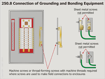
Photo 11
This change clarifies that sheet metal screws are not a suitable means of connecting bonding or grounding conductors to enclosures, nor are they permitted to fasten grounding and bonding lugs, terminals, or other connection devices to enclosures. The revision incorporates the attachment of terminals or other connection devices to enclosures in addition to just wires. The integrity of the connections of grounding and bonding conductors must be established through suitable methods or listed means that meet performance requirements of 250.4(A)(5) and 250.4(B)(4). Connections also must meet the criteria specified in 250.90, which indicate that bonding shall be accomplished in a manner that not only establishes electrical continuity but also ensures an effective connection with the capacity to conduct safely any fault likely to be imposed on them. The revision clarifies that where screws are used to connect grounding or bonding conductors or terminals to enclosures, machine screws or thread-forming screws or other suitable means must be used. The change recognizes products currently in use in the industry that provide thread-forming screws as an acceptable means of fastening equipment, such as equipment grounding terminal bars or conductors of the wire type, to electrical enclosures.
250.30(A)(4)(a)
Grounding Electrode Conductor, Multiple Separately Derived Systems
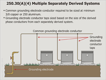
Photo 12
Changes to this section include converting the text into a list format as provided for in 3.3.1.2 of the NEC Style Manual. Rules for sizing the common grounding electrode conductor, sizing the grounding electrode conductor taps, the connection requirements, and installation requirements are now included in 250.30(A)(4). Where the common grounding electrode conductor tap concept is utilized, the size of the common grounding electrode conductor must not be smaller than 3/0 copper or 250 kcmil aluminum as a result of this revision. These more restrictive sizing requirements will provide reasonable assurances that future installations are not likely to result in an inadequately sized common grounding electrode conductor installed using this concept. Installers are still permitted to run a single grounding electrode conductor from an individual system to an electrode in accordance with 250.30(A)(3). In new subdivision (c) Connections, the methods of connecting the grounding electrode conductor taps to the common grounding electrode conductor have been clarified and presented in a list format. The methods permitted have been revised to be consistent with those currently permitted for the grounding electrode conductor tap concept that is currently allowed as an alternative under 250.64(D) for connections of grounding electrode conductors for services. This resolves the conflict and differences between 250.30(A)(3) and 250.64(D) in the 2002 NEC and provides consistency and clarity.
250.50
Grounding Electrode System
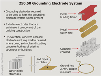
Photo 13
Removing the word “available” is consistent with the requirements of the NEC Style Manual (3.2.1), which states, “The NEC shall not contain references or requirements that are unenforceable or vague.” Table 3.2.1 includes “available” as one such word. The changes to this section provide needed clarification and guidance as to which electrodes are required to form the grounding electrode system. Grounding electrodes listed in 250.52 are generally present because they are an inherent part of the construction of a building or structure. It is clear that if any of the electrodes are present, they are required to be used as part of the grounding electrode system.The new exception exempts concrete-encased electrodes of existing buildings or structures from the main rule where they are not accessible without disturbing the concrete. The term if available as used has contributed to inconsistent enforcement of the requirements and this change should solve that problem. Concrete-encased electrodes normally have low resistance and are considered as reliable electrodes, either as the sole grounding electrode or as part of the grounding electrode system. However, requiring electricians to damage finished concrete in order to get to steel reinforcement bars has not proven to be justified. Some enforcing agencies have deemed it necessary to use reinforcing steel in concrete as the primary grounding electrode because of its reliability and have adopted rules to require that a conductor be attached to the rebars and run so that it is accessible to electricians after the concrete is poured.
310.15(B)
More Than Three Current-Carrying Conductors in a Raceway or Cable
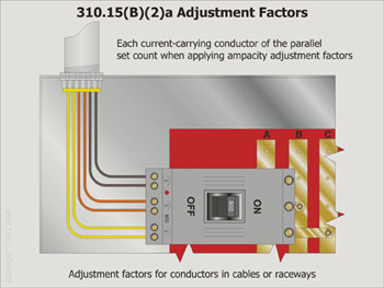
Photo 14
The change made in 310.4 deletes the wording “to form a single conductor” in the rule on conductors in parallel. This wording apparently has been incorrectly interpreted as meaning that conductors in parallel are considered as one conductor when applying ampacity adjustment factor requirements of 310.15(B)(2). While two or more conductors installed in parallel provide what is considered as a single conductive path, they are individual conductors. The removal of the wording in 310.4 and the addition of a new sentence in 310.15(B)(2)(a) should make it very clear that each current-carrying conductor in a circuit is required to be counted when applying ampacity adjustment factors regardless of whether or not those conductors are a single conductor per phase or multiple conductors paralleled together. The example shown above consists of two conductors per phase with a total of six current-carrying conductors. Where they are installed in a single raceway, Table 310.15(B)(2)(a) reduces the allowable current-carrying capacity of each conductor to 80 percent of the values in Tables 310.16 through 310.19.
340.112
Insulation
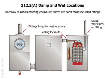
Photo 15
The new wording included in 340.112 as the last sentence under the section title of “Insulation” addresses the rating of underground feeder and branch-circuit cable where used as a substitute for nonmetallic sheathed cable. Type UF cable is permitted by 340.10(4) of the 2005 Code to be used as NM cable where it complies with Parts II and III of Article 334. The reference to the article on nonmetallic-sheathed cable in the 2002 Code was to the entire article. That broad reference raised some questions as to which provisions in Article 334 apply to UF cable. The wording in 340.112 of the 2002 Code did not include any specific information on the temperature rating of conductor insulation where the cable is used in place of NM. The 2005 Code narrows the reference in 340.10(4) to include only Parts II and III of Article 334 by action on Comment 7-160a and the addition of the new sentence to 340.112 makes the temperature rating much clearer. The language added to this section clearly requires that conductors in Type UF cable be rated at 90°C (194°F) where the cable is used as a substitute for NM cable.
344.22
Number of Conductors
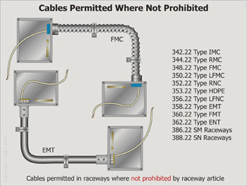
Photo 16
Installation of cables in raceways has been a topic of discussion for many years. Previous editions of the Code specifically permitted cable to be run in short sections of raceway for physical protection but did not directly address the issue of installing cable, such as nonmetallic-sheathed cable, in complete raceway systems. Notes to the tables in chapter 9 included wording on cables in raceways but neither raceway nor cable articles gave any clear direction on that point. The 2002 Code added a second paragraph to the section covering the number of conductors in raceway articles and it included wording that permitted cable to be installed in raceways where it is permitted by the specific cable article. That action provided guidance regarding the use of the raceway but nothing was added to cable articles to specifically recognize cables for that use. The deletion of the word “”permitted”” and the insertion of “”not prohibited”” in its place changes the perspective of this issue. With the new wording, cables are permitted to be installed in raceways unless that use is prohibited by the article covering the cable being used. Code-making panel 7 has the responsibility for articles on cables and has not processed any change in those articles to prohibit cables from being installed in raceways as of the completion of the 2005 Code change process.
376.23(A)
Deflected Insulated Conductors
References in 376.23(A) and 378.23(A) of the 2002 Code were to 312.6(A) for determining the minimum size of wireways but were not specific which column in the table to use. That apparently has resulted in different interpretations as to bending space required for conductors in these enclosures. Where conductors in wireways are deflected and the angle of bend is greater than 30 degrees, the values in column 1 of Table 312.6(A) are to be used in determining the minimum size of wireway permitted. The added wording should make the rule much clearer and provide greater consistency in its application.
404.8(B)
Voltage Between Adjacent Devices

Photo 17
The rule in 404.8(B) prohibits the voltage between snap switches or between snap switches and other devices from exceeding 300 unless a barrier is installed between them. This voltage is not uncommon where 480 Y/277 systems are used to supply electric discharge lighting. The wording “”permanent installed barriers”” left some question as to its exact meaning. Dividers designed for use in boxes to provide separation between devices are normally field installed by being inserted in a slot or other means to form a separate compartment for a device. The deletion of the word “”permanent”” and the addition of “”identified, securely”” provides a much clearer description of what is intended by this rule. The term identified is defined in Article 100 as “”Recognized as suitable for the specific purpose, function, use, …”” and securely indicates to “”hold fast.”” The revised text provides a more readily understood description of the installation and its intended function.
406.8(B)(1)
15- and 20-Ampere Receptacles in a Wet Location
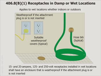
Photo 18
Receptacles installed in wet locations are periodically exposed to water and need protection against water entering the receptacle and enclosure. The 2002 Code wording in 406.8(B)(1) requires receptacles to have covers that remain weatherproof while a cord cap is connected to the receptacle but it addresses only outdoor locations. It was stressed in the substantiation supporting the proposed change that receptacles in interior wet locations are often subjected to the water spray and the same protection provided for outdoor receptacles should be required for those installed in wet locations indoors. The same type of hazard exists whether or not the location is indoors or outdoors. Where indoor locations are determined to be wet locations and receptacles are located in that area, it is likely that those receptacles will have a cord cap inserted in them at some time when the area is hosed down or is subjected to water spray. The expansion of this rule to include indoor wet locations is a logical solution to provide protection for receptacles in those locations just as it does for receptacles installed outdoors in wet locations. The potential of damage by being exposed to water is basically the same for receptacles in either location.
410.73(G)
Disconnecting Means
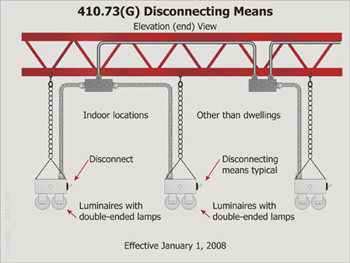
Fluorescent luminaires (fixtures) are often serviced while energized, including the replacement of ballasts. This often requires individuals to work while on or from ladders which allows only limited movement and ability to react to shock incidents where the worker accidentally comes in contact with energized parts. The substantiation included with Proposal 18-93 indicated that this practice of servicing this equipment while energized is increasing, and it presents a real danger to those who do that work. In an effort to provide a safer working condition for those who perform this type of service, a new 410.73(G) has been added to require a disconnecting means to be installed either inside or outside the luminaire that can disconnect all conductors of the ballasts. The type of lighting equipment included in this requirement involves fluorescent luminaires that utilize double-ended lamps and contain ballasts. Five exceptions to this rule are included to cover installations or conditions where variations of the rule are needed or it is not considered practical to apply this requirement, such as in hazardous locations, and in emergency lighting. An effective date of January 1, 2008, allows sufficient time for the industry to prepare to include switches for this type of lighting.
430 Part X
Adjustable-Speed Drives
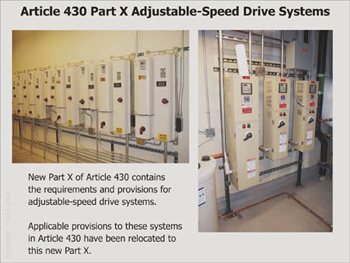
Photo 20
This new Part X of Article 430 contains general requirements for adjustable-speed drives. Sometimes called variable frequency drives, this type of motor controller provides an electronic means to vary motor speed. The substantiation for the new rules indicated that previous editions of the NEC contained insufficient information to properly guide the installer. In an effort to provide a better understanding of some terms used in the new text, three new definitions were added to 430.2. Installation requirements in 430 Part X supplement or modify the general requirements for motor circuits in 430 Parts I through IX. The new rules contain general requirements for determining conductor size and ampacity and several options for overload protection for the drive and motor. Motor overtemperature protection is required with several options permitted. A new fine print note explains the relationship between motor speed, motor current and the need for motor overtemperature protection. The requirement to permit a properly sized disconnect on the supply side of the drive has been relocated to new section 430.128.
517.30(C)(3)
Mechanical Protection of the Emergency System
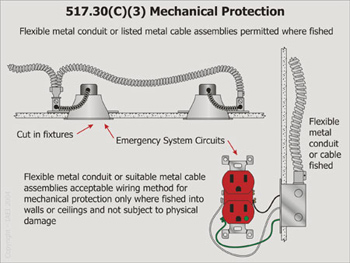
Photo 21
This change retains the basic concept of mechanical protection for emergency systems in hospitals, but addresses practical issues not covered in previous Code language. The fine print note following 517.30(C)(3) in the 2002 Code provided an informational reference to 517.13 for additional grounding requirements in patient care areas. That reference is now in mandatory language as the second sentence in 517.30(C)(3) and states that branch circuits in patient care areas shall comply with 517.13(A) and (B). The change in 517.30(C)(3)(3) allows the use of flexible metal raceways and metal-sheathed cables fished into existing walls or ceilings not otherwise accessible and not subject to physical damage. This limited use of flexible metal raceways and metal-sheathed cables resolves a problem with a practical solution. Remodeled areas, where it is impractical to wire new outlets or equipment using nonflexible wiring without removal of existing wall or ceiling finish, may now be wired with flexible metal raceways or metal-sheathed cables.
600.12
Field-Installed Secondary Wiring
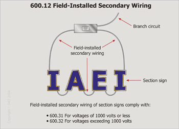
Photo 22
The addition of this new section provides appropriate references into Part II of the article relative to secondary wiring method requirements for section signs. A new definition of the term section sign has also been included in 600.2 for proper correlation and understanding of the term. This new section also specifically references secondary sign circuits with voltages of 1000 volts or less as being required to meet the rules in 600.31, and secondary sign circuits with voltages of over 1000 volts as being required to meet the requirements of 600.32. The significance of this new section is in the references to Part II of the article and the sections that specify the type of acceptable wiring methods for such secondary sign circuit wiring. Listed section signs are required to provide installation instructions relating to the sign sections as well as the interconnecting field-installed wiring. Approvals of the field-installed portion of section signs rest with the authority having jurisdiction (AHJ) as clearly indicated by the product standard and the Guide Card information for these types of equipment.