
In my jurisdiction, we provide electrical inspection training for our combination inspectors twice a month (along with mechanical/plumbing and building code). The ongoing joke among the electrical designers and installers in the area is that the training material is obvious because the correction notices will suddenly reflect the subject of the recent class. Not a bad criticism, I suppose, in that it means people are paying attention and applying what is taught. But the joke reflects a reality that can be counterproductive. The very nature of electrical code training will require a focus on specific code language and application of that language to the intended field installation. Many times, the exception to the code rule is the more frequent application. Concentration on a specific code requirement is necessary for effective training but it can lead to a problem: losing sight of the big picture. What do I mean by the big picture? Electrical design and installation rules exist to address the hazards that are a result of the very nature of electricity. It is critical to present electrical code rules in the context of these general concepts. Realization of the direct relationship between the code rules and the physical nature of electricity is recognition of the big picture.

Photo 1. What is the occupancy?
Although there is no shortcut to NEC knowledge, an understanding of general electrical safety concepts leads to a more complete understanding of the requirements. The NEC cannot be reduced to a set of broad concepts; every specific requirement exists for a reason. Proper application of the code language will require the user to have an understanding of the specific situation addressed by the code. But in my experience, whether attempting to instruct new inspectors with limited electrical background, or those with many years in the trade, presenting a code rule in the context of the general electrical safety concept involved leads to a much better understanding and appreciation for the rule. Another benefit? An understanding of these basic electrical safety building blocks makes the code rules easier to understand and remember. The list of general concepts is not fixed and every instructor may see things differently but we can all agree that there are general electrical safety concepts. The need to explain NEC rules is not limited to the classroom. Every electrical inspector is an instructor; they will have to explain the requirement for those they inspect in the field. Designers and installers are far more likely to comply with the rules when they understand the reason for the requirement.
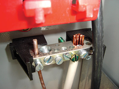
Photo 2. Grounding/Bonding
Keeping a big picture perspective is beneficial when learning NEC requirements and is absolutely essential when applying those requirements during a field inspection. I encourage our inspectors to remember six major electrical safety concepts when inspecting electrical work. Putting all code rules in a six-compartment box is not the intent. The objective is just the opposite: to provide a tool ensuring a comprehensive electrical inspection that includes all relevant NEC requirements. Without a broad based overview, it is too easy to fall into the trap of writing up a list of very specific code violations resulting from non-compliance with one article of the NEC while not even considering the requirements found in other applicable articles. My safety six-pack includes these concepts:
- Wiring Method
- Grounding/Bonding
- Overcurrent Protection
- Supply-Side or Load-Side
- Special Occupancy
- Special Equipment/Conditions
I want to encourage the inspector to consider, at the very least, the six concepts as applicable for every electrical inspection.
All elements work together to produce a safe electrical system. For example, the equipment grounding conductor (EGC) exists as a path for fault current, so that the overcurrent protection (fuse, circuit breaker) will be able to trip properly under fault conditions. If we inspect for the presence of correct overcurrent protection for a feeder or branch circuit without also verifying the correct installation of the EGC, then we have not verified either. Without a path for fault-current, the overcurrent device cannot protect the circuit! The wiring method (raceway) itself may fulfill the EGC requirement, but is the raceway permitted for the specific equipment or occupancy? Or is the circuit in question located on the supply-side of the main disconnect (service)? In that case, there would be no EGC, but supply-side bonding jumpers in the form of conductors or listed raceway (wiring method) connectors would be required. As you can see from the above example, all six elements (and more) can be present in virtually every electrical inspection.
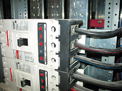
Photo 3. Overcurrent protection
Wiring method
Permitted wiring methods are found in NEC Chapter 3, Wiring Methods and Materials. General and specific installation requirements are provided for each wiring method. Is the installed wiring method appropriate for the location or occupancy? Have the specific installation requirements been achieved (support/secure)? Are the conductors of the correct size and insulation type for the location or occupancy? Do the engineered plans specify a wiring method or conductor size beyond the minimum code rules? All wiring method requirements must be verified as correct (approved) at the rough inspection before being covered by the building finishes.
Grounding/Bonding
The grounding and bonding rules of Article 250 are very important and must be considered for every inspection. Limiting the voltage to earth, providing a path for surge/lightning and fault-current are objectives satisfied by compliance with the rules. Different inspections will require a focus on the various elements of Article 250. When inspecting the electrical service we would be concerned with the grounding electrode system, bonding of the structural steel/metal piping systems, and bonding on the supply-side of the main disconnect. But an inspection for approval of feeder or branch circuits would require a focus on the equipment grounding conductor. A final inspection may necessitate verification of compliance with the grounding/bonding requirements for receptacles and equipment. There will be grounding and bonding considerations for every phase of the installation.

Photo 4. Wiring method
Overcurrent protection
Limiting current to a safe level for conductors and equipment is a basic electrical protection concept. Electrical current that exceeds the rating of a conductor, bus, or equipment will cause heat that can damage the insulation. Extreme overcurrents can even melt the conductor or bus. The two basic types of overcurrents are short circuit and overload. A short circuit is a fault that results when the normal load is unintentionally bypassed by a low resistance path. Quite often the path of the short-circuit current is through grounded metal structures. In that case the short circuit may be called a ground fault. Short circuits result in very high currents limited only by the available fault current of the source. The term overload is defined as currents in excess of the equipment full-load rating or the conductor-rated ampacity. The heat resulting from an overload will depend on the amount of current and the length of time the current flows. Fuses and circuit breakers are the two most common devices used for overcurrent protection. Special overload components are used for specific applications such as motor overload protection. Arc-fault and ground-fault are two other types of electrical circuit protection that can be integrated into the overcurrent protective device. The minimum code rules, manufacturer’s instructions, and the specific installation design must all be considered for approval.
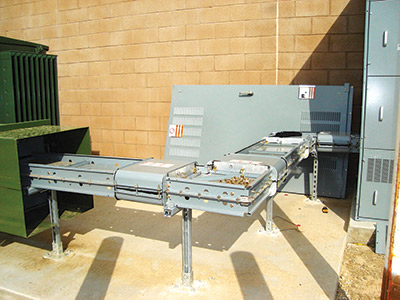
Photo 5. Supply-side installation
Supply-side or load-side
Know where you are in the electrical system as related to the service disconnect. Are you looking at equipment and conductors on the supply-side or the load-side of the service disconnecting means? It makes a difference. The rules for grounding/bonding, permitted raceways and location can be different. As noted above, the equipment grounding conductor does not exist on the line-side of the service disconnect, but there are other rules for bonding (supply-side bonding jumper). There are raceways permitted for use on the load-side of the service that are not permitted for use on the supply-side. See all the specific rules for services in Article 230 Services.
Special occupancy
The general rules of Chapters 1 – 4 of the NEC are modified by the rules of Chapters 5 for the specific occupancy. Chapter 8, Communication Systems is not subject to the first 7 chapters of the NEC unless referenced by the language of Chapter 8. The inspector must be aware of the NEC hierarchy of rules and apply the rules correctly. Is the occupancy under inspection included in Chapter 5? If so, what general rules have been modified?
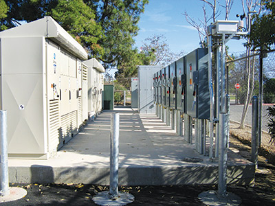
Photo 6. Special equipment
Special equipment/conditions
The general rules of Chapters 1 – 4 are also modified for the specific equipment included in Chapter 6, Special Equipment and Chapter 7, Special Conditions. We must be aware of the equipment and conditions included in the NEC with specific installation rules. Just as important, we must not apply the special rules of Chapters 6 and 7 to general equipment. Will any of the special equipment and conditions listed in NEC Chapters 6 and 7 be a part of your inspection(s) today?
Keep the big picture in focus as you inspect, and know the electrical safety concepts behind the code rules. Bringing your safety six-pack to work with you can be a good way to insure practical and comprehensive electrical inspections.