There is new Rule (4-006) in Canadian Electrical Code 2012 (CEC 2012), with requirements to consider maximum equipment termination temperature in determining the conductor ampacity. This new rule is introduced as part of the conductors’ ampacity harmonization between USA (National Electrical Code – NEC) and Canada (CEC).
However, is this rule harmonized with existing products’ safety standards?
No, it is not, and the discrepancies between Rule 4-006 requirements and the CSA product standards’ requirements will be discussed in details.
Where the rule in the installation code, such is CEC, is not harmonized with the product standards, the application of the rule represents many challenges for electrical contractors, designers, manufacturers and regulators.
The objective of the article is to underline the need for changes in Rule 4-006 in CEC 2015, address some issues in products’ standards, and discuss issues of application of correction factors.
Rule 4-006 requirements vs. product standards testing and marking
Rule 4-006 requires that the temperature rating associated with the ampacity of a conductor be selected and coordinated so as not to exceed the temperature rating of any connected termination or device. Conductors’ sizes must be determined by considering where the conductors will terminate and how that termination is rated. If a termination is rated for 75° C, the maximum temperature at that termination should be 75° C when the equipment is loaded to its ampacity.
There are two separate requirements in Rule 4-006. Subrule (1) provides requirements for equipment marked with temperature termination rating and Subrule (2) deals with equipment that is not marked.
Subrule (1) says, “Where equipment is marked with a maximum conductor termination temperature, the maximum allowable ampacity of the conductor shall be based on the corresponding temperature column from Tables 1, 2, 3 or 4.”
Unfortunately, this is where the problem starts.
CSA Part 2 certification standards for many products require products to be evaluated with conductors with ampacities determined from clauses and tables specified in the standards. For example, in CSA standard C22.2 No. 5 for breakers (this standard is harmonized with UL standard UL 489) there is the requirement that “…each field wiring terminal of a circuit breaker shall have a wire connector that has a capacity acceptable for the number, wire size, and type associated with the circuit breaker. See Table 6.1.4.2.1. …” This is important, since the standard also verifies that the wiring terminal is acceptable for the temperatures encountered.
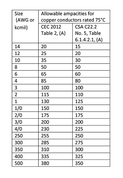
Comparison Chart
So, Comparison Chart compares the copper conductor sizes and ampacities specified in Table 2 of CEC 2012 with copper conductor sizes and ampacities specified in breaker standard for field wiring conductors.
As shown in Comparison Chart and based on the breaker’s standard, the ampacities of the breakers’ field wiring conductors are similar to Table 2 for copper conductors and Table 4 for aluminum conductors. This means that these products [switches and breakers] are never tested with ampacities such as those in Table 1 or 3. Remember, Rule 8-104 limits the maximum continuous load to be 70% of the rating of the overcurrent device when conductors are selected from Table 1 and 3, which is additional safety factor compared to 80% when conductors are selected based on Table 2 or 4 (for 80% rated devices). This is the additional safety factor in CEC for continuous load where conductor ampacities are selected based on Table 1 or 3 that is not considered in Part 2 standards. However, when the load is not continuous, there are no additional safety factors in CEC. Considering the differences in ampacities between Table 1 vs. Table 2, and Table 3 vs. Table 4, regardless of the additional safety factor in CEC for continuous load, selecting the ampacities based on Table 1 or 3 could result in overheated terminations at the equipment.
It is not only a breaker standard that specifies the ampacities of the field-wiring conductors to be similar to Table 2 for copper conductors and to Table 4 for aluminum conductors. Many other products’ standards have similar requirements, just to name some: CSA C22.2 No. 4 for switches; CSA C22.2 No. 14 for control equipment; CSA C22.2 No. 29 for panelboards, etc. For example, CSA standard for panelboards, C22.2 No. 29 is very specific, “For all tests, supply conductors shall be sized in accordance with the 75° C rating of Tables 2 and 4 of the Canadian Electrical Code, Part I, as applicable.”
Don’t forget that a conductor has two ends, and even if the equipment is not marked with the termination temperature rating, the other end of the conductor is likely connected to a breaker or a switch. Even for underground runs, where the ampacity of conductors are determined by the IEEE835 calculation or from “D” Tables in CEC Code, the conductors’ ampacities at the termination shall not exceed values specified in Table 2 or 4, in accordance with products’ standards.
To conclude, in accordance with products’ standards, where conductors are terminated to equipment rated 600 V or less, the selected conductor ampacity shall be based on Tables 2 or 4 in CEC, unless the equipment is marked otherwise.
It is also important to say that products’ standards for testing, for example breakers’ or switches’ standard, specify 75° C or 60° C rated conductors for field wiring.
Currently, there is no circuit breaker or a switch rated up for 600 V or less that is approved for 90° C conductors and their 90° C ampacity.
And, this is where another issue with Rule 4-006 is present.
Subrule (2) says:”Where equipment is not marked with a maximum conductor termination temperature, 90° C shall be used by default.”
Both breakers’ and switches’ standards require products to be marked with 75° C termination temperature if they are tested with 75° C conductors No. 1 AWG and smaller sizes. Otherwise, the products rated 100 A or less are tested with 60° C rated conductors and are not required to be marked!
The same standards specify for equipment rated higher than 100 A (or suitable for conductors larger than No. 1 AWG), the field wiring conductors are required to be rated 75° C. However, both breakers and switches standards do not require any termination marking for devices rated higher than 100 A (or suitable for conductors larger than No. 1 AWG).
It is obvious that marking requirements in these standards are in contradiction with subrule (2) of Rule 4-006, that specifies 90° C as a default if the equipment is not marked with a maximum conductor termination temperature.
There are many unmarked products, such as breakers, switches, panelboards in the market that are tested with 75° C rated conductors.
Permitting the 90° C rated conductors with sizes based on 90° C rating may lead to overheating of the termination.
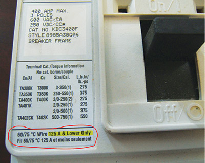
Photo 1 is the example of the confusion in the product’s temperature termination marking, 400-A breaker approved to CSA standards C22.2 No. 5 and marked with “60/75° C Wire – 125 Amp & Lower Only” in the highlighted area.

Photo 1. Confusion in the product’s temperature termination marking.
Does it mean that this 400-A breaker is suitable for 90° C rated field wiring conductors?
- Yes, in accordance with Rule 4-006 and the product marking.
- No, in accordance with CSA C22.2 No. 5 standard testing requirements.
It is worth explaining that in USA where NEC is harmonized with UL products standard, regardless of the marking on this 400-A breaker, NEC specifies 75° C termination temperature rating.
Application of correction factors to 90° C ampacities
Rule 4-006 does not prevent the use of conductors having a temperature rating (i.e., 90° C) in excess of the termination temperature (i.e., 75° C) of the equipment, but such conductors shall have their installed ampacities limited to the equipment termination temperature (i.e., 75° C). Remember this fact when the application of correction factors is discussed.
Let’s consider a typical scenario where conductors with insulation temperature rating of 90° C is terminating on equipment with termination temperature rating of 75° C and there is a need to apply correction factors (bundling and temperature) to these conductors. The stringent approach is to apply the correction factors to the 75° C ampacity of conductors. However, there is an alternative approach that can be considered and does not reduce the safety. In Ontario, Bulletin 4-12-* permits and clarifies this alternate approach. The Ontario Bulletin permits applying the correction factors to the 90° C ampacity of the conductor, with the condition that the corrected ampacity is less than or equal to the 75° C ampacity of the conductor. This approach complies with the intent of CEC Rule 4-006 and harmonizes with NEC.
Therefore, when correction factors are applied to conductors rated 90° C and connected to the equipment with 75° C termination temperature, the installed ampacity of such conductors shall be lesser of:
- the corrected 90° C (e.g., Table 5C factor x 90° C ampacity column of Table 2); or
- the conductor 75° C ampacity (e.g., 75° C ampacity column of Table 2).
The rationale for this approach is that equipment marked with a termination temperature rating is tested with conductors rated at that temperature. If the ampacity of the conductor used does not exceed that which the equipment is tested with, there will be no impact on the ability to dissipate heat from the termination. The correction factors only affect the conductor insulation temperature.
Also, when installation conditions require conductors to be bundled together, it could be assumed that some of the conductors will be flared from each other as they get close to a termination point, and that the operating temperature at the termination will be less than 75° C.
Let’s look at the numerical example shown in diagram 1. The load for each breaker is not continuous, 89A.
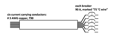
Diagram 1
- Determine the correction factor:
- Based on Rule 4-004 and Table 5C, for 6 conductors – 0.8
- Determine the ampacity of No. 3 AWG copper conductor, 90° C rated:
- From Table 2, 90° C column – 115 A
- Determine the corrected ampacity: 115 A x 0.8 = 92 A,
- Evaluate the termination rating. To comply with Rule 4-006, compare the conductor ampacity at 75° C with the corrected ampacity.
The corrected ampacity of No. 3 AWG conductor is 92 A
Compliance with Rule 4-006 is based on the fact that the corrected ampacity (92 A) is less than 75° C ampacity of the conductor (100 A, based on Table 2, 75° C column).
The overcurrent device (breaker) rated 100 A or 90 A is tested in accordance with CSA standard C22.2 No. 5 with No. 3 AWG 75° C conductors at the rated current to not exceed 75° C.
The installation meets the intent of the Code based on Rule 4-006 requirements for termination temperature and Rule 14-104 requirements for the overcurrent device rating.
Note: If correction factors are applied to the 75° C ampacity, as per stringent approach, the installed conductor ampacity would be 80 A (0.8 x 100 A = 80 A) and the conductor size will need to be larger to comply to overcurrent device, or overcurrent device will need to be changed.
Although not mentioned in the example, CEC Rule 8-104 requirements must be considered to determine the maximum calculated continuous load.
Final thoughts
CEC is a live document, now updated every three years to keep up with the technology change. Hopefully, in the CEC 2015 we will see some harmonization between Rule 4-006 requirements and products’ standards. Do we have any other options? Yes, change products’ standards to always require temperature termination marking, or change products’ standards to permit the products to be designed and tested with 90° C rated conductors with sizes based on 90° C ampacity.
However, considering that the introduction of Rule 4-006 in CEC was part of the harmonization process, and that the NEC is already harmonized with products’ standards, it is reasonable to expect some changes in Rule 4-006 in Code 2015.