Introduction
Photovoltaic (PV) systems that generate electricity from sunlight are being installed in ever increasing numbers throughout the United States and the rest of the world. Over 150 megawatts of PV modules are being produced worldwide annually and these PV modules, when exposed to sunlight, will be generating electricity for the next thirty years and longer. Utility-interactive PV systems (that can feed power to the electrical utility grid) and stand-alone PV systems are being installed in both rural and urban locations on residential dwellings and commercial buildings. They are either utility-interactive or they provide power for lights, water pumps, appliances, and communications equipment in stand-alone applications. A few PV systems are owned and operated by utility companies, but most are not, and they fall under the provisions of the National Electrical Code (NEC) and are inspected by the Authority Having Jurisdiction (AHJ).
This article will briefly describe both stand-alone and utility-interactive PV systems and highlight code issues that electrical inspectors should be aware of when inspecting them.
PV Cells, Modules and Arrays
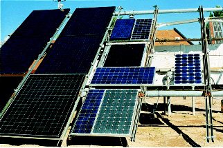
PV modules use solar cells to convert sunlight directly into direct current (dc) electricity. A number of cells are connected in series or parallel to form a PV module, which is the smallest commercially available, listed product for power applications. PV modules range in power output from about six watts to about 300 watts with nominal output volt- ages from 6 to 90 volts (Figure 1, PV module test bed at New Mexico State University). PV modules are connected in series and parallel to increase voltage and current output; these groups of modules form PV panels or arrays. PV arrays may consist of any number of modules (for instance 30 watts or less at 12 volts) up to tens of thousands of modules with megawatt outputs at over a 1000 volts. One of the largest systems was utility-interactive and was installed, owned, and operated by a non-utility organization and, therefore, fell under the NEC.
Photovoltaic cells are made of a number of materials. The oldest commercially available technology uses a silicon material that is processed to produce a final product. Newer technologies are using various thin films to produce PV modules that are expected to lower the cost of the product. The most common PV module uses cells made of silicon wafers that are laminated between a glass front plate and rear insulator (sometimes glass) with an aluminum frame. PV modules made from thin-film photovoltaic materials may be constructed in a similar manner, but some manufacturers are exploring less expensive manufacturing methods such as laminating the PV material directly to metal roofs or producing roofing tiles that also serve as PV modules. Many of the PV modules on the market (manufactured in the US and elsewhere) have been listed to standards established by Underwriters Laboratories (UL) and many also have fire ratings for use on rooftops.
Stand-Alone
There are thousands of residential stand-alone PV systems in the US plus thousands of stand-alone communication sites, water pumping systems, emergency call boxes, and lighting systems. In many states, any electrical system that requires field-installed wiring should be installed according to local codes or the NEC and should be inspected.
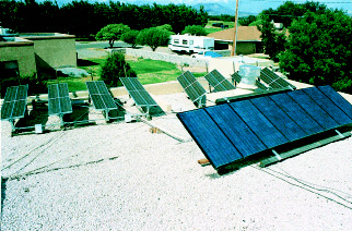
As the name implies, stand-alone systems are not connected to the utility grid and are self-contained producers of electrical power. They may use batteries for energy storage. These systems may also have engine-driven backup generators. A typical residential stand-alone system might have a PV array rated from 1 to 4 kW, a 4 kW inverter, a 1000 amp-hour battery bank, and a 3 to 6 kW backup generator (see figure 2). An engine fueled by gasoline, propane, natural gas, or sometimes diesel fuel would drive the generator. PV systems that include a generator or second renewable energy source such as a wind turbine are known as hybrid systems (see figure 3, Hybrid PV system).
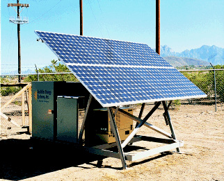
Commercial stand-alone PV systems used for power at telecommunications sites, National Parks, and in military installations may have PV arrays sized from 10 kW to 200 kW with proportionally sized battery banks and backup generators (Figure 4, Pinnacles National Monument PV System).
Remote (and some urban) lighting and water pumping systems may have only a few PV modules. Water pumping systems usually do not have batteries and operate only during daylight hours.
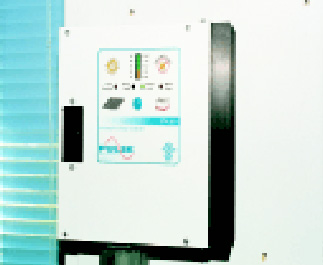
With the addition of a battery bank, most stand-alone PV systems will also have a charge controller to control the charging and discharging of the batteries (Figure 5, Battery charge controller). The charge controller may contain a low-voltage disconnect to protect the batteries from excessive discharge. The low-voltage disconnect may be a separate device. Many inverters have internal low-voltage disconnect controls.
There are more than 1000 utility-interactive PV systems in the U.S. but the number is expected to increase due to federal and state subsidies and the Million Solar Roofs Initiative of the federal government. For more information see the US Department of Energy’s web page at www.eren.doe.gov/millionroofs .
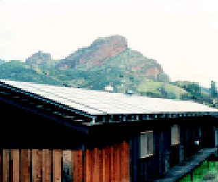
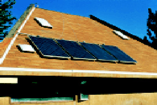
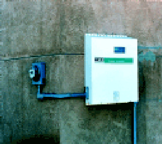
A residential PV system in an urban location will usually be a utility-interactive system (Figure 6, PV modules on roof). The output of the PV array (typically 500-2,000 watts) will be connected to a listed, utility-interactive inverter (dc-to-ac power conversion) (Figure 7, Utility-interactive inverter). The interactive inverter will produce energy only when connected to the electrical power grid that is operating at near 60 Hz and 120 or 240 volts. If the grid is “down” for some reason, the inverter will produce no power and, in fact, will usually stop producing power (de-energize) even in “”brownout”” conditions. This creates a safer environment for the utility lineman by preventing exposure to PV power on lines that have been disconnected from the grid. Because of the NEC requirements to de-energize, utility-interactive PV systems do not pose any of the dangers associated with engine-driven generators that are
illegally connected during outages after a storm.
Utility-interactive PV systems must be connected to the utility with a dedicated circuit. There should be no receptacle or other outlets on this circuit between the inverter output and the load center. Section 690-64(b)(2) places restraints on the size of the PV system that can be connected to any particular load center or other circuit. These restraints are particularly important in commercial installations where the load centers and distribution panels are operated at near capacity.
AC PV Module
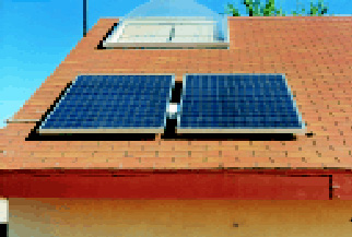
The ac PV module is a new type of utility-interactive PV system (Figure 8-Two ac PV modules). These listed devices have a small (100-300 watt) inverter attached (factory integrated) directly to the back of the PV module or modules (Figure 9, Rear view of ac PV module showing attached inverter). There is no field-connected or installed dc wiring, and the system operates much like an ac appliance. It is listed as a single unit. The only output is alternating current, and there are no accessible dc voltages. The output terminals of the ac PV module are not energized until they are connected to a 120-volt 60-Hz utility grid. This type of PV system may become increasingly popular since the unit cost of these low-power systems is small compared to larger systems with multiple components. The installation and code requirements of the ac PV modules are considerably simplified.
Code Requirements
Article 690 of the NEC specifically addresses installation requirements for PV electrical systems, but most of the rest of the code is also applicable. Where there are conflicts in the code requirements between Article 690 and other articles of the Code, Article 690 takes precedence due to the unique nature of PV modules as electrical generators.
Wiring
Aside from the exposed single-conductor module wiring allowed by NEC Section 690-31, the rest of the wiring, in both ac and dc circuits, should comply with the requirements of Chapter 3 (Wiring Methods and Materials) or Chapter 4 (Equipment for General Use) of the NEC. Exposed single-conductor wiring is not normally allowed by the NEC inside buildings and also should not be used in the well-designed and installed PV system. Flexible, portable power cable (NEC Chapter 4) should only be used in PV arrays where the movements of sun-tracking devices require the extra flexibility.
PV modules and arrays do not have the capability of generating high fault currents like a battery or generator. The PV output is proportional to the intensity of the sunlight on the module. The rated current (both short-circuit and operating) of a PV module is measured in a laboratory under standard test conditions. The standard conditions used for rating may be exceeded in actual use, on a daily basis, for three hours or more. Consequently, the instructions provided with PV modules require that all conductors and overcurrent devices be rated to handle 125 percent of the rated short-circuit current. This requirement was contained in the UL Standard 1703 and the 1996 NEC. In the 1999 NEC, the requirement is contained entirely within the NEC.
Temperature Derating of Conductors
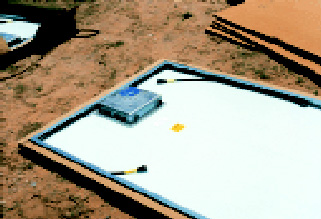
Since PV modules operate at elevated temperatures and the wiring to the modules may be in conduits that are exposed to sunlight and the weather, temperature derating of conductors is necessary. PV modules may operate at temperatures of 20-40°C (68-104°F) above the ambient temperatures. In the hot, sunny Southwest, where ambient temperatures reach 45°C (113°F), the PV module junction box on the back surface of the module may reach 75°C (167°F). Conductors with 90°C-rated insulation should be used, and the ampacities of conductors in the junction boxes need to be derated accordingly. Conductors in conduit are considered to be in exposed locations and should have insulation rated for wet use. For exposed conductors, type USE-2 or type TC cable meets the 90°C/wet requirements. In conduit, conductor types RHW-2, THWN-2, THW-2, or XHHW-2 meet both the 90°C and wet requirements.
Overcurrent Protection
As in other electrical systems, each conductor or circuit in a PV system should be protected from overcurrent. Since a PV system may have more than one source of energy, some circuits may have power sources at both ends thereby requiring overcurrent protection at more than one location. Although PV modules are current-limited power production devices, the UL-listing and labeling may require an overcurrent device for each module or series string of modules to protect the modules and wiring from external sources of power. In most systems with batteries or utility-interactive inverters, the module wiring must be protected from high fault currents originating from the batteries or the utility grid back feeding through the system.
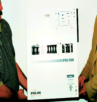
DC source-circuit combiner devices and power centers used in PV systems are somewhat like ac load centers used in conventional ac systems. The individual PV source circuits connected to PV power centers resemble ac branch circuits connected to circuit breakers in an ac load center.
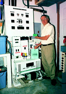
Current-limiting fuses such as the Class RK-5 or Class T fuses are used to protect wiring and devices connected to batteries since large fault currents are possible. Where current-limiting fuses are not used, each overcurrent device in the circuit (either a fuse or circuit breaker) must have an interrupt rating capable of withstanding any fault currents that may occur. Typically, overcurrent devices with interrupt ratings of 20,000 amps or higher are used with battery circuits.
In the dc circuits of a PV system, only overcurrent devices listed for dc operation are allowed by the NEC. Underwriters (UL) Standard 1703 and the 1996 NEC require that the voltage rating of the overcurrent devices should be at least 125 percent of the rated, open-circuit voltage of the PV array output since rated open-circuit voltage increases as temperatures go below 25°C (77°F). In the 1999 NEC, a new Table 690-7 includes the UL 1703 requirement and provides correction factors that are less than 125 percent for localities where the modules will experience more moderate temperatures.
Disconnects
The requirement for disconnects for PV systems are covered in Article 690 of the NEC. Generally, a disconnect is needed for each source of power or energy storage device in the system. If these disconnects are inadequate to isolate equipment like inverters and charge controllers for servicing, additional disconnects may be required for these components.
PV modules and arrays are energized when illuminated, but a disconnect at the PV array location is not required by the NEC unless the system is so large (more than 10 kW) that subarray disconnects would facilitate maintenance actions. Usually, only a single disconnect for the PV array is used near the power center or other combiner box (stand-alone systems), or near the inverter (utility-interactive systems). This main PV disconnect disconnects the entire PV array from all equipment, thereby removing the PV source of power from the system. It also isolates the PV array and array wiring from all other sources of power in the system, but it does not make the array safe for maintenance. All switchgear used in dc circuits are required to be appropriately listed and labeled for use in dc circuits.
Ground-fault Protection
Section 690-5 (Ground-fault Protection) of the 1999 NEC requires that any PV array installed on a dwelling be provided with ground-fault protection (changed from the 1996 term “”Ground-fault Detection and Interruption””) to minimize the possibility of fires. This NEC requirement is unique to PV systems and is not related to the common GFCIs used for shock protection or the ground-fault equipment required on high-current circuits used for equipment protection. Utility-interactive inverters may contain ground-fault protection circuits or the ground-fault protection is available as an option. Stand-alone and utility-interactive PV systems that are roof-mounted on dwellings need ground-fault protection. AC PV modules generally are meeting the requirement with equipment-type, ground-fault-protection-circuit breakers installed as part of the dedicated branch circuit for those modules.
Listed Equipment Availability
Listed hardware for PV installations is now commercially available. Listed combiner boxes and power centers that contain the necessary overcurrent devices are sold as components (Figure 10, Listed Power Center). Several inverters with power outputs of less than 5 kW are listed. A number of listed battery charge controllers are now on the market. Components (such as inverters) for larger systems are not listed yet and may have to be examined for safety. Conventional junction boxes, pull boxes, conduit, and other familiar materials are used throughout the systems.
Batteries and Engine-generators
Batteries are covered in Article 690 of the NEC. The installation of batteries, their use in dwellings, allowable operating voltages, current limiting, battery interconnection, and charge control are all spelled out. Batteries and engine-generators generally are not listed. Batteries may either be sealed types (valve regulated lead-acid—VRLA or gelled electrolyte) or the more common flooded lead-acid batteries. All batteries can vent hydrogen gas when over-charged and they contain an electrolyte. Both types of batteries should be installed so that the exposed terminals are not accessible to unqualified persons. The flooded batteries should be installed in an acid resistant, non-conducting container to contain spilled electrolyte in the unlikely event that the battery case is damaged.
While the batteries should be installed in a well-vented area, power venting is not required for small systems. Hydrogen gas is very difficult to contain and normal room ventilation is usually adequate to ensure dispersion of the gasses. Venting manifolds common to each cell should be avoided. Conduit entrances to battery enclosures should be below the tops of the batteries since hydrogen gas rises, and the conduit ends need to be sealed with an appropriate material to prevent hydrogen gas from entering power centers or other switchgear.
Installations
Typically, PV power systems are installed by persons trained and experienced in one discipline or trade. The code-familiar person such as an electrical contractor or electrician may be unfamiliar with the unique particulars of PV system installations. Conversely, the PV system designer or vendor is often an expert on PV installation requirements but is not familiar with the intricacies of the NEC. For this reason, the most satisfactory installations are the result of a team effort, from project commencement to completion, that includes a PV designer, an electrical contractor/electrician, and the Authority Having Jurisdiction (AHJ).
Summary
Photovoltaic power systems have been installed throughout the US and increasing numbers are being installed each year. Most of these systems fall under the requirements of the National Electrical Code. Equipment, knowledge, and experience is available that allows these systems to be installed in full compliance with the NEC. Best results are obtained when a PV systems designer works with an electrician or electrical contractor and the Authority Having Jurisdiction.
Additional Information
A manual entitled Photovoltaic Power Systems and the National Electrical Code: Suggested Practices authored by John Wiles and published by Sandia National Laboratories is available without charge from the author or on the internet at www.sandia.gov/PV .
The author writes a bi-monthly column called Code Corner in Home Power Magazine, which covers the NEC requirements for PV energy installations in some detail. The magazine is available on the Internet at http://www.homepower.com/ and subscriptions are available by calling 800-707-0836.
Presentations by the author on PV systems and the NEC® are available to groups of 30 or more electrical inspectors, electrical contractors, electricians, and other interested IAEI members. The presentations run from 6-8 hours and consist of overhead and 35mm slides and hardcopy handouts.




Find Us on Socials