Severe weather events in the Winter of 2023/2024, including heavy, long-duration rain and snowstorms, tornadoes, flooding, forest fires, high winds, and thunderstorms, have resulted in power outages where tens of thousands and hundreds of thousands of people have been without electrical power for hours, days, and weeks. Where property damage has not been severe, many homeowners are considering installing a photovoltaic (PV) electrical power system with energy storage to provide electricity during extended periods of power outages. It is anticipated that many of these battery-backed-up PV systems will be installed in the coming years as the power outages become more extreme due to continuing extreme weather events. This article will cover some of the basics of these systems that the AHJ should be aware of and possibly inspect before giving a permit for energizing the system and connecting it to the utility.
Several manufacturers are making these energy storage PV systems. They include Enphase, Generac, Panasonic, Tesla and others. New companies are joining the industry while others are leaving. One of the first things the inspector should ask about is the equipment listing or certification by Underwriters Laboratory (UL) or other United States Nationally Recognized Testing Laboratory (NRTL). Certifications by countries outside the United States are not acceptable in most jurisdictions.
This article will focus on the systems designed and sold by Enphase since the author has some experience with two of these systems. These two systems are small demonstration systems, but the equipment, the design process, and the installation would be similar to larger systems.
System Overview. The operation of these systems varies from manufacturer to manufacturer. In general, there is a software-driven control system, a utility interactive inverter(s), and an energy storage device. The system can accept alternating current (AC) grid power, when available, to power the main loads and protected loads as well as charge the batteries. The PV system, in this case providing AC power when sunlight is available and AC voltage is available at the output terminals of the microinverters, can be used to charge the batteries if needed, and power the protected loads. In this example, the AC voltage at the PV array microinverter output terminals is provided by the energy storage system (battery), which in this example has internal bidirectional microinverters and carries AC input and AC output power on the same circuit depending on whether the energy storage system is being charged or discharged.
The system with software control has several options in the routing and delivery of energy through the system. Various utility-required energy vs time usage and/or delivery profiles may be stored internally and selected. Some utilities prohibit energy back-feed into their system, and the Enphase system can be programmed for this function. In this case, all PV production is used on site and will effectively reduce the site energy draw from the utility, lowering the site utility bills.
The output of the PV system or the grid may be selected to be the primary charging source for the energy storage system. In some cases, the utility grid may have a time period selected, possibly at night, when the batteries are charged using the grid.

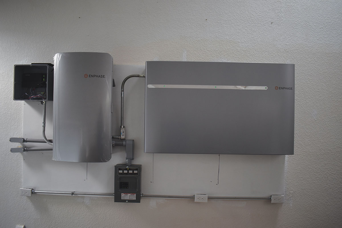
System Description. See the lead in picture. The large horizontal rectangular device in this picture is the Enphase 10T energy storage system (ESS). This energy storage device is somewhat unique in that it has alternating current (AC) inputs and outputs. Internal to the system are a number of microinverters, each connected to lithium-ion batteries (see photo 1). These microinverters are bidirectional and can accept AC input currents for charging the lithium-ion batteries and DC currents from the lithium-ion batteries to produce AC output currents. The charge management process is integral to the energy storage system and is not accessible to the installer except under factory-directed maintenance actions.
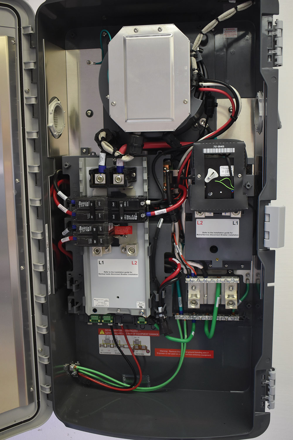
To the left of the energy storage system is the Smart Switch (a.k.a. ENPOWER), which contains a high current busbar, a power control system (PCS), and various internal relays controlling power flow (see photo 2). This device also includes positions for optional circuit breakers for input and output circuits and an installed circuit breaker for the internal neutral forming transformer that is required because the energy storage system provides only 240 volts, but the system must be able to power 240-volt and 120-volt AC loads.
Slightly below and to the right of the Smart Switch is the protected loads load center which contains circuit breakers for each of the three protected load circuits in this demonstration system. One circuit has a 15-amp, 240-volt breaker for the IQ Envoy monitoring and communications device, and there are two 120-volt circuits for the demonstration-protected loads (see lead-in photo).
Control and Communications. Above and slightly to the left of the Smart Switch is the communications device known as the IQ Envoy. The Enphase system is quite complex in terms of how it controls various currents. There is a current transformer on the AC output of the PV system measuring total PV production. There are two current transformers that can be optionally installed to monitor the currents going to the protected loads. The outputs of these current transformers are monitored by the IQ Envoy, which communicates via powerline signals to and from the microinverters associated with each PV module and via Wi-Fi with the control systems in the Smart Switch and in the energy storage system (see lead-in photo). The Envoy also communicates to the factory website via Wi-Fi and/or cellular modem with appropriate connected devices.
The inspector may find it informative and useful to download from the factory web site the two or three installation manuals associated with the Enphase battery system. These installation manuals will highlight the mechanical and electrical requirements and procedures for the installation of the various pieces of equipment involved. There is also a YouTube video showing the actual steps required to upload the single-line diagram and system calculations required by one of the installer certification courses.
The Process
Coursework. Enphase requires that a potential installer take at least four online courses and pass them, as well as submitting a single-line diagram, design information, and a site plan for an Enphase system. The amount of information required in these submissions is significant and is reviewed by highly qualified personnel at Enphase before they are accepted.
Installation. The installer will typically use what is known as an Enphase Installer Tool Kit, which is a downloadable application for cell phones or tablets that goes through the entire system commissioning process step-by-step, with calculations required in many steps before the next step can be started. This toolkit standardizes the installation process but also requires reference to the installation manuals for each piece of equipment when that equipment is addressed by the toolkit. Knowledge and reference to the National Electrical Code (NEC) requirements are also needed as the installation progresses.
Mechanical. While electrical inspectors normally inspect only the electrical installation of a particular system, the overall quality of workmanship must be evaluated and ensured for complete system safety. Although these systems are modular in nature and consist of individual sections mechanically and electrically combined, significant planning is required and how they will be mounted and where they will be mounted to ensure the mechanical safety of the system and the building structure. The various equipment sections, some of which weigh nearly 100 pounds (each of the Enphase 3T battery sections) and require two people to lift to mount them on a metal bracket that is fixed to the wall. The total weight of the Enphase 10T energy storage system may approach 500 pounds when attached to the building wall. The instructions indicate that these metal brackets should be firmly connected to several studs within the wall. Unfortunately, in some cases, the predrilled holes in these brackets may not align with multiple studs spaced at 16 or 24 inches. This was the case for the installations I monitored, and the solution was to screw a 4 x 8-foot x 3/4-inch piece of plywood to the wall with the plywood firmly attached to four studs in the wall with multiple screws. The metal bracket was then screwed with the required number of shorter screws to the plywood resulting in a stiff, structurally sound mechanical installation ready for the heavy equipment sections that would be attached to the metal bracket. Smaller devices, such as the Smart Switch, use a smaller bracket that can be attached to a single stud, but again, where possible, multiple studs should be used.
Each piece of equipment has specific locations for electrical conduit attachment points or cable entry points. Enphase and field-purchased equipment will be electrically connected, and there are preferred requirements for the location and relationships of the various pieces of equipment. Getting acceptable Wi-Fi reception is a must for the system to operate properly. This means that the equipment layout should be planned with care before attaching the equipment to the wall. If not done carefully and properly, complex routing of cables and conduits may be required.
Of course, the mechanical mounting procedures cannot be viewed after the equipment is mounted on the wall and the AHJ should query the installer as to his process for ensuring that the mechanical installation is safe. For example, how were the wall stud locations identified? What types and lengths of fasteners were used?
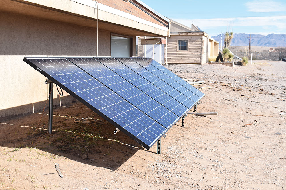
The ground-mounted PV array consists of 6 JINKO 295 W PV modules with Enphase IQ 7A microinverters (see photo 3). The module frames and racking system are well grounded to earth. The microinverters are double insulated and isolated from the ground, and only a two-wire, 240 V connection is required to the Smart Switch. In this small demonstration system, a PV string combiner is not required since there is only one string in the PV array.
Electrical Design.
Calculations. The Enphase system is modular and can be expanded to some extent, if deemed necessary during the design process, to deal with greater numbers of protected loads to be powered in the event of utility and/or PV outages. Yes, snow covering the PV system or extremely cloudy weather happens during extreme weather events when the power from the utility may not be present. And, of course, at night, there is no PV energy.
The total power draw in terms of watts from the protected loads must not exceed the power delivery capability of the energy storage system (ESS-battery) in the selected Enphase system. Also, the starting surge current from the largest motor-driven load must be less than the ability of the Enphase system to deliver those surge currents. A soft start kit is recommended for motors having high starting surges. Additionally, Enphase limits the ratio of the PV output current to the battery size to eliminate the possibility of unstable operation of the internal power control and charge management systems.
During the system design process using the Installer Tool Kit, Enphase requires that these various electrical parameters be calculated and submitted to the factory, so they should be readily available to the AHJ on request.
NEC Issue or Not? The internal busbar in the Smart Switch is rated at 200 A but a careful examination of the sizes of optional circuit breakers feeding the busbar reveals that the NEC required 120% rule may be violated when certain sizes are selected. However, the internal power control system (PCS) has been designed to deal with this and has been certified by Underwriters Laboratory as meeting safety requirements.
Enphase and other manufacturers may specify the conductor sizes that can be used with various circuit breakers and equipment terminals. However, it is up to the installer to select conductor sizes based on the currents in the specific system. For example, the smallest available circuit breaker that can be installed in the Smart Switch for both the protected load circuit output and the main utility input circuit is a 100-amp breaker. This normally requires a 2 AWG conductor; the breaker terminals are sized for that conductor. Larger terminal sizes on higher-rated breakers are used, but currents in a small system may have much smaller currents. These smaller currents would allow the use of smaller conductors, which presents a challenge for the installer. It would violate the listing on the circuit breaker or terminal lug to use a conductor smaller than the conductor specified for the terminal or lug. One way to address this issue is to splice a short length of 2 AWG conductor to the smaller conductor and use that to connect to the large breaker terminals on the 100-amp breaker.
Also, the manufacturer may suggest a certain size 90°C conductor for a certain application but did not adjust the conductor size with the circuit breakers that usually specify that 75°C ampacity values be used for the attached conductors. The installer must make these NEC-required adjustments based on the system design.
Another requirement to be cautious about is that the internal Smart Switch breaker for the energy storage system output will carry bidirectional currents and needs a safety retaining device to clamp the breaker to the busbar. An Eaton circuit breaker is required, but it is a special breaker with a “B” as the last letter in the part number, indicating that the breaker has a hole for an optionally attached hold-down device. These special breakers are normally not stocked by local distributors but may be special ordered or obtained directly from Enphase.
Internal or External Circuit Breakers? The Smart Switch has circuit breaker positions on the 200-amp busbar for the output of the PV system (20-60A), the connection to the energy storage system (20-60A), the input from the utility (100-200A), and the output to the protected loads (100-200A). Using these internal circuit breakers is optional and depends on the circuit arrangement and how and where the external circuits to the Smart Switch are protected. If the external overcurrent protection devices, usually circuit breakers, are to be located near the Smart Switch (within a foot or two), internal overcurrent protection devices are not used.
However, if any of these overcurrent devices are some distance away from the Smart Switch or are out of sight, then overcurrent devices should be installed in the Smart Switch for each of the circuits. As mentioned above, one of the requirements for completing the installer certification course is to submit a single line diagram, a site plan, and calculations for the various conductor sizes involved. The site plan and the single line diagram require that the conductor length for each circuit be specified and the line-of-sight distance between the endpoints of the circuit also be specified. For example, how far from the Smart Switch is the circuit breaker in the main utility panel in terms of conductor length and line-of-sight distance (see photo 4)?
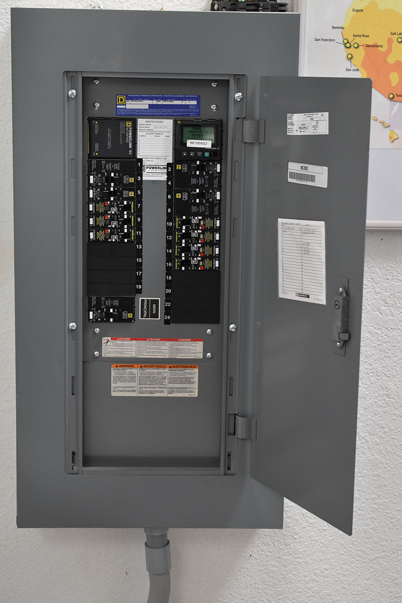
In this case, the conductor length was about 55 feet, and the line-of-sight distance was about 35 feet, which indicated that a circuit breaker for the utility input should be installed in the Smart Switch. The smallest breaker for this purpose that could be installed in the Smart Switch was a 100-amp breaker on the utility input. However, the PV breaker in the main utility panel was only a 50-amp breaker which was adequate for the demonstration loads in the system. To minimize the voltage drop and meet ampacity requirements, a 6 AWG conductor was selected for this circuit. To justify this size conductor with a 100-amp breaker in the Smart Switch, calculations had to be provided to show that the available current that could be sent from the Smart Switch to the utility under fault conditions was restricted to 50 amps. In fact, the breaker from the PV system was a 20-amp breaker, and the breaker from the energy storage system was a 30-amp breaker, which were the two sources that could feed power to the utility. Also, a short circuit in this conductor would probably cause the 50-amp breaker in the main panel to open and the Smart Switch to stop supplying power to this circuit.
In effect, the 100-amp breaker in the Smart Switch is merely a disconnecting device and the 6 AWG conductor is protected because of the limited currents that can be sourced at the Smart Switch into that conductor. This is another area where the power control system internal to the Smart Switch provides additional protection over what NEC requirements normally dictate.
The Inspection Process. The complexity of the systems dictates that the system be connected to the grid to complete the full commissioning process and verify that the system is operating correctly. This generally means there should be a discussion between the installer, the utility, and the AHJ to determine how this activity will be carried out. The AHJ may conduct an initial inspection to verify the system’s mechanical installation and electrical connections and the various calculations involved. The AHJ would then issue authorization to connect to the utility, which would have to be approved by the utility. Then a subsequent inspection would be required to verify that the system is operating as designed. Each jurisdiction and utility will have to work out the details of this process for these more complex systems.
Summary
Severe weather events are predicted to become more common in the foreseeable future. These weather events have and will result in large-scale power outages, which may last for hours, days, or weeks. These power outages are expected to increase sales and installations of PV systems with energy storage systems to provide power during utility outages.
These systems are becoming increasingly more complex with software-controlled operating systems and interconnected subsystems communicating with Wi-Fi, powerline signals, and cellular devices. When inspecting the systems, it behooves the AHJ to spend some time in the plan review stage reviewing the various installation and operation manuals for the systems. This is necessary because there are significant mechanical installation requirements as well as complex electrical interconnection requirements that will generally exceed NEC requirements.