Article 690, Solar Photovoltaic Power Systems, has been in the National Electrical Code (NEC) since 1984. An NFPA-appointed Task Group for Article 690 proposed changes to Article 690 for both the 1996 and 1999 codes. The Task Group, supported by more than 50 professionals from throughout the photovoltaic (PV) industry, met seven times during the 1999 code cycle to integrate the needs of the industry with the needs of electrical inspectors, and end users to ensure the safety of PV systems. The Task Group proposed 57 changes to Article 690 and all the changes were accepted in the review process. The performance and cost of PV installations was always a consideration as these changes were formed, but safety was the number-one priority. All of the proposals were well substantiated and coordinated throughout the PV industry, and with representatives of Underwriters Laboratories, Inc (UL). The Task Group was led by Ward Bower of the Photovoltaic System Applications Department at Sandia National Laboratories. Ray Weber, Chair of Code-Making-Panel #3 (CMP-3) requested the formation of the Task Group for Solar Photovoltaic Systems. Paul Duks of UL provided valuable background information and technical coordination with applicable UL standards.
The most significant changes that were made in Article 690 for the 1999 NEC, along with some of the rationale, are discussed in the remainder of this article.

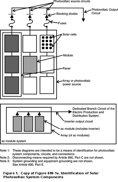
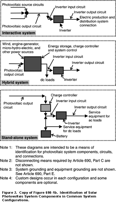
Figure 690-1, often a source of confusion to many who thought it was a design diagram for a PV system, has been completely revised and expanded to identify the PV-unique components in various types of PV systems and to show how they may interrelate. A copy of the new Figure 690-1 is shown as Figure 1 and Figure 2 of this report.
Many definitions in Section 690-2 (Definitions) were updated and clarified and five new ones were added to define the terms used in Article 690. For example, the term “”power conditioner”” was replaced with the more commonly used term “”inverter.”” All references to solar hot water control systems were removed. The new and evolving ac PV module was defined as an Alternating Current Module to retain consistency of terms used in the NEC®. Definitions related to stand-alone, hybrid, and utility-interactive systems were added or revised to better define each and to include the hybrid PV systems. The common terminology appearing in Section 690-2 will aid the Authority Having Jurisdiction (AHJ) and PV installers to better understand the systems and to communicate more effectively during the installation and inspection process.
Section 690-4 (Installation) was revised to clarify the interconnections of modules. This change allows “”daisy chaining”” modules from junction box to junction box as long as ampacity and temperature requirements for wiring and devices are met. New language in 690-4 also allows interconnected modules in systems under 50 volts to be considered as a single-source circuit.

Section 690-5 (changed from Ground-fault Detection and Interruption to Ground-fault Protection) for the PV array on dwellings, was revised extensively to provide clarity and to allow alternative methods to satisfy the requirement for ground-fault protection while still maintaining system safety. Listed equipment that may be included in utility-interactive inverters, power centers, and as separate components is now available to meet this requirement. This fire-protection requirement on dwellings (which will hopefully never be needed) is now well defined. The hard-to-define term “”disable”” was removed from this section and from Section 690-18. Providing an indication of a fault and labeling the hardware is required in the 1999 edition. The fact that ground-fault protection equipment may automatically disconnect the grounded conductor of an array in the event of a fault is also covered with the requirement for a warning label placed near the ground-fault indicator.
A new Section 690-6 (Alternating-Current Modules) was added to fully define the connection requirements of ac PV modules. Among other things, a ground-fault protection device is required on the dedicated branch circuit used for connecting the ac module to the load center. That protection device is required to disable the ac module. Disabling an ac PV module is accomplished by removing the ac grid connection. Since the duplex outlet on a receptacle type GFCI violates the dedicated circuit requirement, a service entrance panel or blank face device must be used. This ground-fault protection requirement is intended for fire protection on dwellings and not shock protection. Ground-fault equipment protection circuit breakers that fit in the service entrance panel or in a separate panel and that trip at 20-30 milliamp are suitable.
The changes in the 1999 Article 690 will require changes in the documentation for calculating maximum voltages and currents for PV modules. Today, the UL requirements for PV modules are found in the instruction manual of listed modules. The old UL standard 1703 required the instruction manual to state the requirements for multiplying module open-circuit voltage and short-circuit current by 125% before going to the NEC. With the 1999 changes, those UL requirements have been included in Article 690-7 (Maximum Voltage) and 690-8 (Circuit Sizing and Current) of the NEC. Section 690-7 includes a new Table 690-7 that now makes the voltage multiplier a function of the lowest expected ambient temperature. Only when the expected temperature reaches -21°C (-5°F), does the factor increase to 1.25 as found in the old UL1703 standard. If the modules are to be installed where the coldest expected temperature is a balmy 10-25°C (50-77°F), then the correction factor on open-circuit voltage is only 1.06. Section 690-7 also limits the maximum voltage on one- and two-family dwellings to not more than 600 volts.
In a similar manner, Section 690-8 was revised to include the 125% solar enhancement multiplier required for PV source circuit and PV output circuit current calculations previously found in the PV module instruction manual as part of the listing documentation. Section 690-8 now includes both the 125% multiplying factor required to deal with daily variations in PV module output and the 125% multiplier used to derate all conductors and overcurrent devices throughout the code. The combined factor of both 125% multipliers for PV source and output circuits is 156%, while all other circuits in the system are subject to only a single 125% multi-plier or the 80% conductor-derate required throughout the code.
The new NEC language for system voltage and circuit current calculations for wire sizes requires careful coordination with the UL Standard 1703. The new 1999 NEC requirements may conflict with the UL Standard 1703 until it is modified to remove the solar enhancement and voltage temperature requirements from the module instruction manuals. In the meantime, there may be modules in the pipeline that still have the UL requirement in the instruction manual. Those using the 1999 NEC are now cautioned not to duplicate the solar enhancement requirement.
Section 690-9 (Overcurrent Protection) now has exceptions that do not require overcurrent devices on some types of circuits. These exceptions generally apply to small, single-module, direct-connected water pumping systems where there is no chance of high fault currents from other sources.
It should be noted that overcurrent devices in PV source and output circuits should be rated at 156% of the short-circuit currents from the modules. Obviously, with this rating, these overcurrent devices will not respond to fault currents solely from the connected modules. They will, however, protect the module conductors from backfeed currents from other sources such as parallel-connected modules, batteries, and even currents from ac sources back feeding through inverters.
Section 690-10 (Stand-Alone Systems) is a new section that should benefit the installer and owner of stand-alone PV systems. The code now allows the PV system inverter ac current output to be less than the rating of the building load center or service entrance equipment. A 500-watt inverter may now be connected to the input of a 120/240-volt, 200-amp load center for stand-alone applications. The conductor that is used for this connection has to be rated to carry only the 500-watt output of the inverter, not the 48,000 watts that the service entrance can carry. Also, Article 690-10 spells out that a single 120-volt inverter may be connected to a 120/240-volt load center when certain conditions are met. There must be no 240-volt circuits and no multi-wire branch circuits in the building. Of course, appropriate overcurrent devices must be installed at each end of this cable unless a tap rule as found in Section 240-21 (Location in a Circuit) can be applied.
Section 690-13 (Disconnection Means, All Conductors) was revised to clearly state that a switch, fuse, or circuit breaker should not be placed in a grounded conductor except where the grounded conductor is automatically interrupted to comply with the ground-fault protection required in Section 690-5.
AC PV modules may be grouped together on a single circuit, and a single disconnect-device for all modules is allowed according to additions in Section 690-15 (Disconnection of Photovoltaic Equipment). Ampacity calculations using the sum of the maximum output current of the ac modules still apply.
Section 690-17(Switch or Circuit Breaker) and 690-33 (Connectors) allow the use of a connector for a disconnect-device as long as it is listed for the use and meets other code requirements for polarization, guarding, personnel safety, and grounding. This applies to conventional systems and to ac PV modules.
The markings required on ac PV modules are listed in a new Section 690-52 (Marking, Alternating-Current Photovoltaic Modules). These markings are similar to those required for conventional PV systems required in Section 690-51.
Utility-interactive systems received considerable attention in the 1999 NEC because of the expected proliferation of these systems. Marking the points-of-connection of these systems is required by Section 690-54 (Interactive System Point of Connection). Most of Part G (Connection to Other Sources) was revised to allow easier connection of utility-interactive systems while still maintaining high levels of safety. The changes included a revised requirement for using listed equipment in interactive systems, a new requirement for inverters to de-energize upon loss-of-utility in interactive systems, allowable unbalanced grid connections, and a clarification of the allowable point-of-connection for a PV system.
Section 690-72 (Storage Batteries, Charge Control) was revised to require control of the charging process except the 1999 changes require no battery charge controls on systems where the maximum charging currents are very low (less than 3% of battery capacity expressed in amp-hours).
A new Part I (Systems Over 600 Volts) was added to Article 690 to specifically address PV systems operating over 600 volts. Some of the larger utility-interactive systems may operate above 600 volts. The new section directs that systems greater than 600 volts meet the requirements of the new Article 490 (Equipment, Over 600 Volts, Nominal) that has been added to collect all parts of the code for over 600 volts into one Article. The new Section I defines the maximum battery voltage as the highest voltage experienced under charging conditions. Maximum system voltage is used for the PV source- and output-circuits.
The 1999 NEC Handbook (available from NFPA) includes significantly more detail, substantiation, and explanations of Article 690 and the changes that were made for 1999. It is also an excellent reference for other articles of the NEC.
If you have questions about the implementation of PV systems following the requirements of the NEC, feel free to call, fax, email, or write John Wiles at the location below. Sandia National Laboratories sponsors the activities in this area as a support function to the PV Industry. This work was supported by the United States Department of Energy under Contract DE-AC04-94AL8500. Sandia is a multi-program laboratory operated by Sandia Corporation, a Lockheed Martin Company, for the United States Department of Energy.


Find Us on Socials