Electrical inspectors involved with aerial high voltage facilities frequently have to determine whether electrical conductors are in compliance with the National Electrical Safety Code (NESC). In the July/August issue, I discussed level spans, spans where the conductor points of attachment on the structures are at the same elevation. Inclined spans, spans where the conductor points of attachment on the structures are not at the same elevation, are much more difficult to determine clearances. The minimum clearances of Table 232-1 must be met under three conditions of maximum sag; whichever produces the largest final sag.
- Conductor temperature 120° F.
- The maximum conductor temperature for which the line is designed to operate if greater than 120° F.
- Conductor temperature 32° F. with radial thickness of ice as specified in Rule 250B for the loading district concerned. To determine if a line conductor is in compliance with the NESC, we must know the sag of the conductor under the above three conditions. For example, let’s consider an inclined 900 foot span of 954 kcmil.
Conductor identification is important. If someone tells you the conductor is 954, that’s not enough information. There are two 954 AAC (All Aluminum Conductors): 37 strand and 61 strand. There are also five 954 ACSR conductors (Aluminum Conductor Steel Reinforced). In this example, we will use 954 AAC 61 strand identified by the Aluminum Association as “Goldenrod.” For simplicity, let’s assume the ground under the span is flat and level. The conductor height of attachment at one structure is 153 feet. At the other structure, the conductor height of attachment is 72 feet. Because the grade is not often flat and level, it is difficult to determine at which point the conductor is closest to the ground. For that reason, I usually take numerous conductor height measurements including one at mid-span. You will recall that for a level span, the conductor elevation is lowest at mid-span. For an inclined span, the lowest conductor elevation is shifted toward the structure with the lower height of attachment. In both cases, knowing the conductor height at mid-span is important for our calculations. It is best to measure the conductor heights relative to a common elevation. I usually use the ground level at the base of the pole of higher conductor attachment height. As you may have guessed, a transit or telescope level is a necessary tool when taking field measurements. For our example, let’s assume the conductor height above ground at mid-span is 52 feet and the conductor temperature at the time of measurement is 70°F.
Diagram A
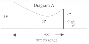
Diagram 1
To understand the calculations necessary to determine the ground clearance, one must have a clear understanding of the relationship between a level span and an inclined span. Mathematically, an inclined span is a piece of a level span.
Diagram B shows the conductor at a conductor temperature of 70°F. To determine the ground clearance C we must know the position of the conductor at maximum sag.
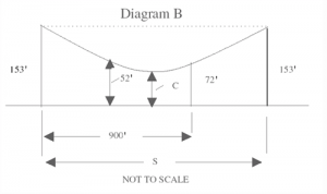
Diagram 2
The following method is one way of calculating the desired clearance. This method is relatively easybut also inaccurate. The error in this method can be as much as 11%. If you use this method, I recommend that you multiply the calculated sag by 1.11 to correct for the error. If a more accurate clearance is necessary, the long method will have to be used.
The first step is to find the conductor horizontal tension H and the level span length S. (See diagram B.)
To find S and H we have two equations:
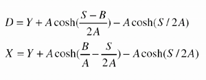
Formula 1
where
D= height of the conductor at mid-span above the level of the base of the pole with the higher conductor height attachment.
For our example D = 52′.
X = the height of attachment of the conductor on the pole with the lower height of attachment.
For our example X = 72′
Y = the conductor height of attachment on the pole with the higher height of attachment.
For our example Y = 153′
B = level span length
For our example B = 900′
cosh = hyperbolic cosine trig function
The two equations can only be solved by substitution. There is only one value of S and A that satisfies both equations. With the help of a computer S = 1200 and A = 1689.54. H can be calculated from A as follows:
H = A x W
where W is the conductor weight per foot in pounds. For 954 AAC “Goldenrod”
W = .8961 lb./foot
H = 1689.54 x .8961
H = 1514 lb.
Next, we need to calculate the conductor vertical tension V:
V =L x W
2
where L is the conductor length in feet.
L = 2A sinh (S/2A)
L = 1225.38′
V =1225.38′ x .8961
2
V = 549 lb.
The conductor total tension T is
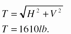
Formula 2
The conductor average tension =

Formula 3
= 1562 lb
The average tension 1562 is the final tension limit we now put into a sag/tension computer program at 70°F. to determine the conductor’s maximum sag. One example of a sag/tension computer program is the Alcoa Sag 10®. The loading table for the heavy loading district should look something like this.
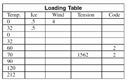
Loading Table
The ruling span should be set to 1200′. Running the program should give us the following:
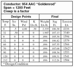
Conductor Table
From the above results, the conductor sag at 120°F is 109.31′. The conductor sag at 32°F. with 1/2 inch of ice (heaving loading district) is 107.13′. The conductor sag at maximum operating temperature for which the line was designed is 112.26′ (212°F). The maximum sag is 112.26′.
Since the “shortcut” calculation was used, we need to multiply the maximum sag by 1.11 to correct for calculation error 112.26 x 1.11 = 124.6′.
The height of the conductor above the ground at maximum sag is 153 – 124.6 = 28.4′.
Unless the ground under the span is traversed by vehicles taller than 14′, requiring a clearance greater than 18.5′, the span is in compliance with the 1997 NESC. The more accurate calculation method takes three times longer and is beyond the scope of a short article.


Find Us on Socials