The arc-fault circuit interrupter (AFCI) is emerging as a new device in the National Electrical Code and in residential installations to enhance electrical safety. New technology generally fosters questions and concerns about the workings and application of the technology and this article will address some of the most frequently asked questions surrounding AFCI:
- How does the AFCI work? and,
- What is the state of the National Electrical Code regarding AFCIs?
This article addressees both questions.
What is the Purpose of an AFCI?
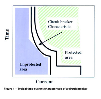
Figure 1. Typical time-current characteristics of a circuit breaker
We need to think about why the AFCI was developed in order to assist our understanding of how they work. Its purpose is to eliminate certain unwanted arcs as potential, electrical fire causes. Electric arcs operate at several thousand degrees Celsius at their center. They also generate a pressure wave that will blow molten metal or burning material from their center onto ignitable materials. Either the high temperature or the materials discharged from the center of the arc can cause a fire. The intent of the AFCI is to detect hazardous arcing and turn off the circuit in order to greatly reduce the potential of fire from an arc.
Since an overcurrent protective device (OCPD), a circuit breaker or fuse, will detect and interrupt an arc above the OCPD characteristic curve, circuits are already protected against these higher current arcs. The AFCI addresses arcs below and to the left of the characteristic curve of an overcurrent protective device. The blue colored area in figure 1 represents the unprotected area in which the AFCI detects potentially harmful arcs.
Arcing Fault Hazards
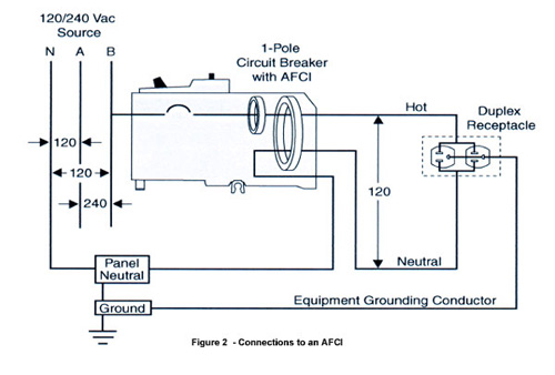
- Figure 2. Connections to an AFCI
Hazardous arcing faults may occur in any of three configurations:
- Line-to-neutral,
- Series (such as in a broken or frayed wire or at a loose connection),
- Line-to-ground.
Line-to-neutral faults will generally be at higher current levels, close to the system available short-circuit current at the point of the fault. In a study done by Underwriters Laboratories for the Electronic Industries Association (EIA), data shows that available short-circuit current at receptacles in residences ranges from approximately 75 A to 1650 A with an average of 300 A for 15 A branches and 467 A for 20 A branches.1 This data gives a good idea of the current levels available in branch circuits and it is for this reason that the point contact tests for AFCIs in UL 1699, Underwriters Laboratories Inc. Standard for Safety for Arc-Fault Circuit Interrupters, are done at 75 amperes and greater.
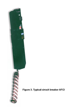
Figure 3. A typical circuit breaker AFCI unit.
A research program conducted during the development of UL 1699 indicated fire ignition of test materials with arcs of 5 amperes and higher. For this reason, tests identified as carbonized path tests in the Standard are done with arcing currents of 5 amperes and greater.
The purpose of this section is not to examine the testing standard or arc phenomena in depth, but rather to get an idea of how an AFCI works. So far, we know that the AFCI must detect a hazardous arc with current levels up to those of an overcurrent protective device characteristic. It must be capable of opening the circuit when one is detected. It must distinguish between hazardous arcs and normal circuit conditions involving arcs or signals that look like an arc. (See Figure 2)
How Does an AFCI Work?
Any statement about how AFCIs function today may be changed by the introduction of a new product tomorrow that employs a different technology. However, we can gain a general idea of how they work by understanding that the current and voltage waveforms of an arc have some distinctive characteristics.
Today’s AFCIs employ two complementary methods of detection: arc recognition and ground fault detection. We will look at each of them.
Arc Recognition
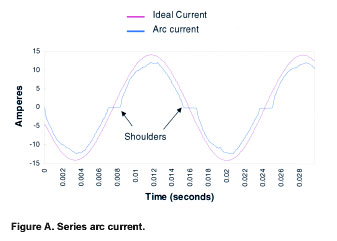
Figure A. The simple case of arcing current in a resistive circuit
The information in the sidebar tells us that voltage and current waveforms will exhibit some unique characteristics including the following:
- Flat “shoulders” in the current around current zero
- Arcing current lower than ideal current
- Voltage across the arc approaching a square wave
- Voltage spikes each half cycle as the arc ignites and extinguishes
- High frequency “noise”
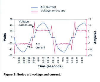
Figure B. The simple case of arcing current in a resistive circuit
Voltage and current signals can be taken by an AFCI unit connected as indicated in figure 2. The connections and current transformer coils indicated in figure 2 constitute one method of obtaining the circuit information for the unit. There may be many other means of obtaining the same information. The AFCI unit will use the circuit information to perform an analysis to determine whether an arc is present and whether it is an arc that should be interrupted. It will very likely be looking for several simultaneous indications of arc presence and persistence in order to verify that the signal is from a hazardous arc. On determining that a hazardous arc is in the circuit, the unit signals interruption of the circuit.
Ground Fault Detection
In evidence from fires caused by electrical arcing, line-to-ground leakage is involved, if not the direct path of the fault in many of the instances. Since an arcing fault is probably in the process of burning away insulation, there is a high likelihood that stray current will reach a path to ground. The path might be through metal appliance housings, fluids, equipment grounding conductors or conduit. Where arcing is involved, a frequent path is arc tracking across insulation that has pyrolyzed (carbonized) from the heat of the arc.
Since line-to-ground faults are a major factor in hazardous arcing faults, present manufacturers have included equipment level ground fault detection as an integral part of the AFCI detection system. Unless labeled otherwise, this ground-fault protection is not the 6-milliampere protection intended for personnel. That is, it is not GFCI protection unless so labeled. For present products, it is a 30-milliampere protection of the kind employed for protection of heating tape and other equipment.
The UL 1699 Standard does not require the 30-milliampere detection level. In fact, it requires detection at 5 amperes and above for faults to ground because it is at the 5-ampere level that fire causes are evident from research experiments. However, since the lower level ground-fault technology is readily available, some manufacturers have chosen to incorporate it.
Forms of AFCI
The UL 1699 Standard covers a number of types of AFCI, each to protect against unwanted effects of arcing.
The Branch/Feeder AFCI is a device installed at the origin of a branch circuit or feeder to provide protection of branch circuit and feeder wiring. This device also provides limited protection to appliance and extension cords. The B/F AFCI is available in circuit breaker form today but is not limited to that form.
The Outlet Circuit AFCI is a device installed at a branch circuit outlet to provide protection of appliance and extension cords. A likely form is a receptacle outlet. It may provide feed-through protection to cords connected to receptacles on its load side.
The Combination AFCI combines the functions of the B/F and OC AFCI in a single device. It is intended to protect branch circuit and feeder wiring and appliance and extension cords.
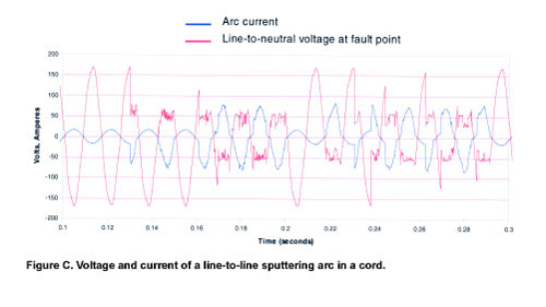
- Figure C. Figure C shows a trace of current in a cord to a 10 A resistive load when the cord is cut by a “guillotine” similar to a paper cutter.
The Portable AFCI is a plug-in device intended to be connected to a receptacle outlet and which is provided with one or more outlets. It is intended to provide protection to connected appliance and extension cords.
The Cord AFCI is a plug-in device connected to a receptacle outlet, to provide protection to the cord connected to it.
The Standard does not specify the form of any of the types, which will allow them to emerge into the marketplace as needed for a specific application. This discussion will focus on the B/F AFCI, since it is the type the inspector may expect to see to meet the new National Electrical Code requirement. The B/F AFCI is presently available in the form of a circuit breaker that also incorporates the AFCI function. Figure 3 shows a typical circuit breaker AFCI unit.
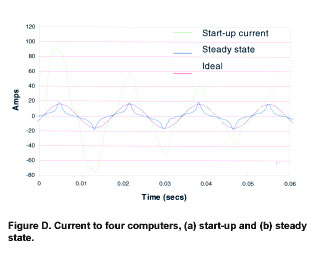
Figure D. Figure D shows the current trace of four computers all energized at the same time and then reaching steady-state current.
These units provide all overcurrent protection functions and ratings of a standard circuit breaker and simply add the AFCI function. When a potentially hazardous arc is detected, the sensing unit signals the circuit breaker to trip and open the circuit breaker contacts. These units are intended to be installed in existing load centers in the position of a standard single-pole circuit breaker. Connections are similar to those of the circuit breaker and ground-fault circuit interrupter (GFCI). They have interrupting ratings, series ratings, SWD and HACR ratings similar to the circuit breaker of the same type.
AFCIs and the NEC
The new Section 210-12(b) of the 1999 National Electrical Code (NEC) reads:
“(b) Dwelling Unit Bedrooms. All branch circuits that supply 125-volt, single-phase, 15- and 20-ampere receptacle outlets installed in dwelling unit bedrooms shall be protected by an arc-fault circuit interrupter(s). This requirement shall become effective January 1, 2002.”
The revision cycle for the 2002 NEC has started with 20 proposals to revise Section 210-12 and two for other articles.
At this point in the development of the 2002 NEC, Code-Making Panel 2 has retained 210-12 much as it is in the 1999 NEC. They deleted the word “receptacle” from “receptacle outlets” resulting in a slight expansion of the requirement to include all bedroom outlets including lighting outlets. They also deleted the statement about the 2002 effective date. Panel statements make clear that they are not immediately ready to expand the requirement for this new technology for which little public experience exists. They were also clear in acknowledging the potential for reducing fire causes with AFCIs. A number of testimonials to AFCI effectiveness in detecting arcing faults appeared in proposal substantiations.
Section 210-12 with the revision requires AFCI protection of 15- and 20-ampere branch circuits, which means that the AFCI must be the Branch/Feeder type. This B/F type has been commercially available since 1998 and is presently the only type commercially available.
Of the two proposals not related to 210-12, one was for Article 230 to require AFCIs to be installed in service equipment when it is replaced in existing dwellings. CMP 4 has not accepted the Article 230 revision. The other proposal was for Article 550 to require AFCIs in bedrooms and living areas of mobile homes and manufactured homes. CMP 19 acted favorably on the Article 550 proposal but only to mirror the 210-12 requirement for protection of bedroom outlets.
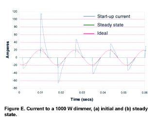
Figure E. Figure E shows traces of a dimmer with a 1000-watt tungsten lamp load.
The state of Vermont has adopted Section 210-12 with an early effective date of January 2001. They are also requiring AFCIs in circuits feeding receptacle outlets in living areas of dwellings in addition to those of bedrooms.
Wrap Up
The AFCI is still an emerging product. Arc detection is accomplished through recognition of arc characteristics in circuit waveforms. Ground-fault detection at 30 milliamperes is added by today’s manufacturers for excellent protection with avoidance of possible nuisance operation. Arc detection technology is becoming better understood by circuit design engineers which means that we can expect even better detection with experience. Indications are that the 2002 NEC will retain installation of the AFCI as a requirement for bedroom circuits in dwellings. There is still an opportunity for comment prior to the December Report on Comment meetings.
1 Fact-Finding Report on an Evaluation of Branch-Circuit Circuit-Breaker Instantaneous Trip Levels, (Underwriters Laboratories Inc., October 25, 1993).
Arc Characteristics
As might be expected, arc current and voltage waveshapes are generally not simple sinusoids. This section shows several current and voltage traces from arcing conditions. Also shown are non-arcing conditions with characteristics that might seem similar to an arc. These are just examples of the countless loads and conditions that may be encountered in residences. An arc-fault circuit interrupter (AFCI) must accurately distinguish between an arc and needed energy if it is to be effective.
Resistive Load in Series with an Arc
Figures A and B show the simple case of arcing current in a resistive circuit. Notice that arc current is less than the ideal current due to the voltage drop across the arc. An arc looks much like a resistor element in a circuit and will frequently have a constant voltage drop of between 20 and 30 volts across it. Also, notice that “shoulders” appear on the current traces around the current zero locations. The arc ignites only after sufficient voltage across the gap returns following a current zero. It extinguishes when voltage drops below that needed to sustain the arc. Arc voltage is almost a square wave except for the transient near current zero. The choppiness of the voltage wave indicates another distinct characteristic of the arc, which is that of a high frequency voltage source.
With a series arc present, the rms value of current and I2t sensed by an overcurrent protective device in the circuit is less than it would sense without the arc. In other words, an overcurrent protective device would be less likely to operate effectively with a series arc in the circuit than without.
Sputtering Arc
Figure C shows a trace of current in a cord to a 10 A resistive load when the cord is cut by a “”guillotine”” similar to a paper cutter. This action might simulate metal furniture cutting the cord, causing a line-to-neutral fault. Voltage shown is that across the cord ahead of the cut. Available short circuit current is 70 A.
The arc is not continuous. Once it starts, it is interspersed with segments of normal load current. Again, the rms value of current and I2t delivered is considerably less than that of a solid fault, especially when viewed over several cycles. The shoulders are again visible in the arc current trace of Figure C.
Switching-mode Power Supplies
Figure D shows the current trace of four computers all energized at the same time and then reaching steady-state current. Shoulders similar to those for arcing current are present in both start-up and steady state traces due to the high harmonic content of the load. Start-up current has characteristics similar to those of an arcing short circuit. Such loads as this must be allowed to start and run without activating an AFCI.
Dimmer
Figure E shows traces of a dimmer with a 1000-watt tungsten lamp load. This load waveform also has trace shoulders and high peaks with similarities to a sputtering arc.
Traces of arc current and voltage illustrate that:
1. Current with an arc in series has a lower rms value than current without the arc due to extinction and re-ignition around current zero.
2. When a sputtering arc exists in a line-to-line fault, the rms value or I2t delivered over several cycles is considerably less than that of a solid fault.
3. Voltage across the arc has characteristics of a square wave with some high frequency noise.
Information in this sidebar extracted from George D. Gregory and Gary W. Scott, “The Arc-Fault Circuit Interrupter, An Emerging Product,”IEEE Transactions on Industry Applications, September/October 1998, pp. 928-933.