Overcurrent protection for electrical equipment can be accomplished by several different methods. The general rules for overcurrent protection of conductors and equipment are found in Article 240 of the National Electric Code. Section 240-2 indicates Article 440 shall be used for protection of air-conditioning and refrigerating equipment. In Part C of Article 440, specifically Section 440-21, the Code states that the requirements of Part C of Article 440 are in addition to or amend the basic requirements in Article 240. This means that the rules in Article 440 are required to be used to obtain proper overcurrent protection for air-conditioning and refrigeration equipment. The process used to size protective devices and circuit components is similar to the process used with other types of motor-operated equipment. The proper application of overcurrent protection rules for air-conditioning and refrigeration equipment can be made relatively easy by following a few basic steps as outlined in this article. To better understand the Code rules, the characteristics of these types of motors must be understood.
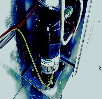
Photo 1. The overcurrent protection requirements differ slightly than those for standard electrical motors
The Hermetic Refrigerant Motor-Compressor
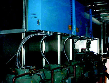
Photo 2. The overcurrent protection requirements differ slightly than those for standard electrical motors
Hermetic refrigerant motor-compressors differ from standard electric motors in a couple of distinct areas. First, a hermetic refrigerant motor-compressor is different from a standard electric motor because it has no external shaft. The motor itself operates in the refrigerant in a sealed housing. Second, these hermetic refrigerant motor-compressors do not have a horsepower rating. The hermetic refrigerant motor-compressor is rated instead by the rated-load current, which is the average current the motor will draw under normally loaded conditions. Third, hermetic refrigerant motor-compressors employ a unique method of cooling. The motor windings and bearings are kept cool by the refrigerant. This characteristic shapes the overcurrent protection requirements. A hermetic refrigerant motor-compressor can be worked much harder than a standard motor. While the motor is operating, the compressor transforms the refrigerant into a liquid, which cools both the motor and the refrigerated product or space. The cooling characteristics depend on the type of refrigerant used, the flow rate of the liquid, and other factors such as flow rate and density. Therefore, the manufacturer of the equipment determines the characteristics of the overcurrent protection system. For this reason, the overcurrent protection requirements differ slightly than those for standard electrical motors (see Photos 1, 2, and 3).
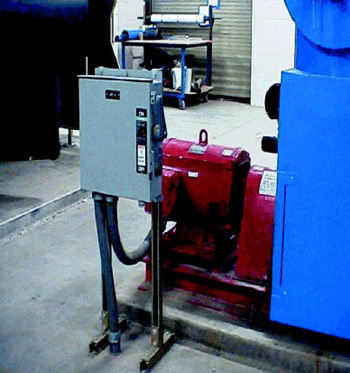
Photo 3. The overcurrent protection requirements differ slightly than those for standard electrical motors
The Two Types of Motors
The first task is to understand the difference between a standard motor and a hermetic motor-compressor. Understanding the differences between the two types of motors enables us to apply the proper Code rules. Section 440-3 requires installations of air conditioning equipment that does not employ a hermetic refrigerant motor-compressor to follow the rules of Article 430, 422, or 424 as applicable.
It is easy to make mistakes. Take, for example, the fan coil units of a walk-in dairy case. Although the function of the fan-coil unit is to cool the walk-in cooler or freezer, the fan coil unit only employs standard motors blowing cool air across a set of refrigeration coils (see Photos 4 and 5). The fan coil unit is required to comply with the requirements for motors in Article 430. Unless the equipment employs a hermetic refrigerant motor-compressor, the Code requirements of Article 440 are not applicable.
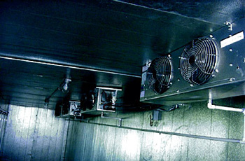
Photo 4. Although the function of the fan-coil unit is to cool the walk-in cooler or freezer, the fan coil unit only employs standard motors blowing cool air across a set of refrigeration coils
The second task is to understand that the rules of Article 440 are in addition to, or amendatory of, Article 430 and other articles of the Code. The rules for motor circuits in Article 430 are the foundation of the special requirements for hermetic motor-compressors. Other applicable Code rules apply in any situation where Article 440 does not modify or amend those rules.
The Nameplate of Combination-Load Equipment
Air-conditioning and refrigeration equipment that employs only a single hermetic refrigerant motor-compressor shall comply with Parts C and D of Article 440. The equipment label or nameplate will state the rated-load current, locked-rotor current, nominal voltage, phase, frequency, and other data. The installer must provide overcurrent and overload protection per Parts C and D.
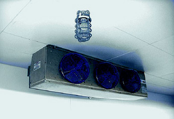
Photo 5. Although the function of the fan-coil unit is to cool the walk-in cooler or freezer, the fan coil unit only employs standard motors blowing cool air across a set of refrigeration coils
We will focus on the combination-load equipment. This type of equipment is more common than a single motor unit. An example of combination-load equipment would be a typical air-conditioning unit. One unit will contain several different loads in combination that comprise the total electrical load of the equipment. This type of equipment will contain at least one hermetic refrigerant motor-compressor. It may also contain a cooling fan or two and possibly a crankcase heater for the compressor. Thus this type of equipment is considered as combination-load equipment.
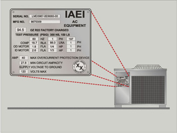
Figure 1. The two most useful numbers are the minimum circuit ampacity and the maximum overcurrent protective device
There are several alternative methods to provide proper overcurrent protection for the equipment covered by Article 440. The combination-load equipment manufactured today should have a nameplate. The nameplate details the data needed in order to provide proper overcurrent protection for the equipment. Section 440-4(b) requires that combination-load equipment be provided with a nameplate that gives the installer and inspector valuable information. The information on the nameplate includes the manufacturer’s name, voltage, phase, rated-load amperes, etc., and two very important items. The two most useful numbers are the minimum circuit ampacity and the maximum overcurrent protective device (see Figure 1).
Some equipment data plates indicate “Minimum Overcurrent Protective Device” ratings. The rating indicates the minimum size fuse or circuit breaker needed to allow the motor to start without nuisance tripping. If present, both minimum and maximum ratings must be followed in selecting the proper protective device.

Figure 2. For combination-load equipment having a nameplate as required by Section 440-4(b), the branch-circuit conductors are required to be “not less than the minimum circuit ampacity marked on the” nameplate of the equipment
The Branch Circuit Requirements
The branch-circuit conductor size requirements for hermetic refrigerant motor-compressors are located in Part D of Article 440. The sizing requirements for the branch-circuit conductors are very similar to those requirements for standard motors. Basically, the branch-circuit conductors are required to be sized at 125 percent of the rated-load current of the single hermetic motor-compressor or 125 percent of the branch-circuit selection current, whichever is less. However, for combination-load equipment having a nameplate as required by Section 440-4(b), the branch-circuit conductors are required to be “not less than the minimum circuit ampacity marked on the” nameplate of the equipment (see Figure 2). See NEC Section 440-35.
The manufacturer has already calculated the conductor size to be based on the total of all of the motor loads in the combination-load equipment times 125 percent. It is not necessary to do these calculations again. For this type of equipment, the installer and the inspector only have to install and verify that the branch-circuit conductors supplying the equipment have an ampacity equal to or greater than the minimum circuit ampacity marked on the nameplate of the equipment.
The Branch-Circuit Short-Circuit Ground-Fault Protection
The nameplate data is also used to select the proper size or rating of the branch-circuit short-circuit and ground-fault protective device. The manufacturer may limit the choice of devices. Fuses and/or HACR rated circuit breakers are normally used for this type of protection.
The branch-circuit short-circuit ground-fault protective device for hermetic refrigerant motor-compressors is required to not exceed 175 percent of the motor-compressor rated-load current. The rating or setting of the protective device may be increased if the initial setting is insufficient for the starting current. The maximum rating or setting is limited to 225 percent of the rated-load current of the motor-compressor or the branch-circuit selection current, whichever is greater. See Section 440-22(a) of the Code.
A hermetic motor-compressor draws locked-rotor current at startup. The branch-circuit short-circuit ground-fault protective device is permitted to be increased by these percentages to allow the motor-compressor to start without tripping the overcurrent device. However, for combination-load equipment, the Code requires that the nameplate be marked to indicate the maximum rating of the overcurrent protective device. The manufacturer has again already done the calculation for the installer or inspector. No additional calculations are necessary in the field to size the overcurrent protective device.
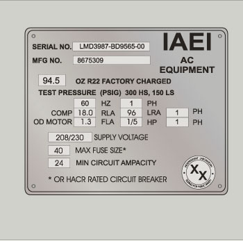
Figure 3. Be sure to use a HACR rated circuit breaker if so indicated on the nameplate
Sometimes the manufacturer of the combination-load equipment will specify fuses as the overcurrent protective device. This is important information and must be followed. If the nameplate says fuse only, the equipment has been evaluated and tested only with a fuse. The manufacturer has determined that only a fuse provides the proper overcurrent protection for the hermetic refrigerant motor-compressor and the other internal components. Use of a circuit breaker would be in violation of the Code Section 440-4(b) and 440-22(c). This would also be in violation of Section 110-3(b). This is the equivalent of not following the manufacturer’s instructions provided with the equipment. Not following the instructions is the same as not following the Code.
Most manufacturers permit either fuses or HACR circuit breakers as the protective device. If the equipment is marked “maximum fuse size*” and the * at the bottom of the nameplate indicates “or HACR circuit breaker” then the equipment has been evaluated and tested for use with either form of overcurrent protection. A HACR breaker is a type of circuit breaker that is listed for group applications. In other words, the breaker is able to supply proper protection for both the larger compressor motor circuit as well as the components of the smaller fan motor circuit. Be sure to use a HACR rated circuit breaker if so indicated on the nameplate (see Figure 3).
The “maximum overcurrent protective device” rating is the other very important number on the data plate. The overcurrent protection device marked on combination-load equipment is marked “maximum” such as “maximum fuse size.” This means that specified size cannot be exceeded. The device could be less than that maximum size.
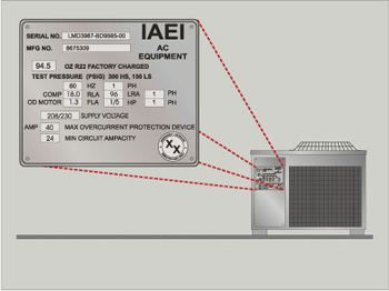
Figure 4. Values on a typical air-conditioning unit nameplate
It may seem that the conductors are improperly protected. However it is the combination of the maximum size short-circuit and ground-fault protective device together with the overload protection system of the equipment that is providing the overcurrent protection for all circuit components. If the overload protection is field-installed for a hermetic refrigerant motor-compressor, the overload sizing must be in accordance with Section 440-52 and must not exceed the manufacturer’s values.
In Figure 2, the nameplate indicates the minimum circuit ampacity and the maximum overcurrent device. Based on the nameplate data the conductors are required to be capable of carrying 27.8 amperes. Remember, with combination-load equipment the 125 percent factor is already used by the manufacturer to determine the 27.8-ampere total. A No. 10 THWN copper conductor is an acceptable size for the circuit conductors. The maximum overcurrent protective device marked on the equipment is 40 amperes. It appears as though the No. 10 THWN conductors are improperly protected. This is not true. The 40-ampere fuse or HACR circuit breaker provides the short-circuit and ground-fault protection. The overload protective device limits the normal running current to the proscribed values.
The overcurrent protective device could be a device rated smaller than 40 amperes as long as it can handle the starting and running current of the equipment. These maximum values are often misunderstood to be the only size allowable by the Code, when in fact it is the value that must not be exceeded.
Equipment Requiring Two Supply Voltages
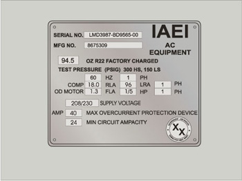
Figure 5. Consequently, since the equivalent full-load current of this A/C unit is 19.3 amperes, the next higher rating must be used, and the disconnect switch must have a minimum of a 5-horsepower, 230-volt, single-phase rating
Air-conditioning and refrigeration equipment that requires two supply circuits at different voltages is required to be marked with a nameplate indicating the minimum circuit ampacity and maximum overcurrent protective devices required for each of the circuits supplying the equipment. This can appear on the same nameplate but it is more common to see individual nameplates. It is not uncommon to see a refrigeration compressor rack in a grocery store that requires the two circuits [see Section 440-4(b)].
Disconnecting Means Rating
The rules in 440-12 determine the minimum rating and interrupting capacity of the disconnecting means. Where the air-conditioning or heat pump compressor unit consists of a hermetic refrigerant motor-compressor(s) in combination with other loads, such as the fan motor, the horsepower rating of the disconnecting means is based on the summation of all currents at both rated-load condition and also at locked-rotor condition. For example, using the values on a typical air-conditioning unit nameplate, (see Figure 4) the 18-ampere rated-load current (RLA) of the compressor motor is added to the 1.3 ampere full-load current (FLA) of the fan motor.
The total of 19.3 amperes is then considered to be the equivalent full-load current for the combined load. According to NEC Table 430-148, the full-load current rating of a 230-volt, single-phase, 3-horsepower motor is 17 amperes, while the full-load current rating of a 230-volt, single-phase, 5-horsepower motor is 28 amperes. Consequently, since the equivalent full-load current of this A/C unit is 19.3 amperes, the next higher rating must be used, and the disconnect switch must have a minimum of a 5-horsepower, 230-volt, single-phase rating (see Figure 5).
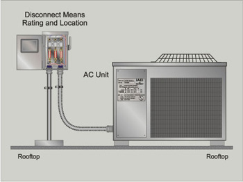
Figure 6. Section 440-14 requires a disconnecting means for air-conditioning and refrigeration equipment to be located within sight from the equipment it supplies
The ampere rating of the disconnecting means must also be at least 115 percent of the sum of all currents at rated-load condition. This minimum rating would then be 115 percent x 19.3 amperes = 22.19 amperes. If the disconnecting means includes or serves as the branch-circuit overcurrent protection for the unit, the rating required for the overcurrent device, rather than this minimum rating, would generally be the determining factor in sizing the disconnecting means. A fused disconnect switch containing either the maximum or minimum sizes of fuses listed on the nameplate would exceed this 115 percent minimum requirement. If an unfused disconnect switch is used as the disconnecting means, however, then this 115 percent rating and the horsepower rating would establish the minimum switch rating.
There is one other consideration in establishing the correct size of the disconnecting means serving the air-conditioning unit. The disconnecting means rating must also be based on currents at locked-rotor condition. Refer to NEC Table 430-151(A) for the conversion of locked-rotor current (LRA) to horsepower. In our example, the nameplate indicates that the motor-compressor LRA is 96 amperes. Since the nameplate does not give a LRA for the fan motor, we assume it to be six times the FLA or 6 x 1.3 amperes = 7.8 amperes. Adding this to the motor-compressor LRA of 96 amperes gives us an equivalent LRA for the combined load of 103.8 amperes. Again referring to NEC Table 430-151, we find that for a single-phase, 230-volt motor with a 103.8 amperes motor locked-rotor current, the disconnect switch should be based on a 5-horsepower rating. See NEC Section 440-12.

Photo 6. The disconnecting means may be located on or within the air-conditioning or refrigerating equipment.
Trying to use the nameplate ratings to size the disconnecting means can be confusing. For example, consider the nameplate information “minimum circuit amperes = 26″ and “maximum overcurrent protective device = 35.” Is a 30-ampere disconnect suitable for use with this particular unit? This is why the locked-rotor ampere marking is important. Since there is no horsepower rating on the hermetic refrigerant motor-compressors, the locked-rotor equivalent must be obtained by using the values in Table 430-151(A) or (B), as appropriate. Using the rated total load amperes of the equipment, we can determine if the disconnecting means has a sufficiently large horsepower rating. Disconnect switches having the same ampere rating may have different horsepower ratings. Installers and inspectors should carefully observe the markings on both the equipment and the disconnecting means. The rating of the disconnecting means is especially critical for larger equipment. Disconnecting means for equipment with an equivalent horsepower rating in excess of 100 horsepower are required to comply with Section 430-109. If general duty switches are used as disconnecting means for equipment exceeding 100 horsepower, the disconnecting means is required to be marked “Do Not Operate Under Load.” The installer normally applies this additional marking.
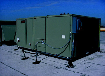
Photo 7. The disconnecting means may be located on or within the air-conditioning or refrigerating equipment.
Location of the Disconnecting Means
Section 440-14 requires a disconnecting means for air-conditioning and refrigeration equipment to be located within sight from the equipment it supplies (see Figure 6). The disconnecting means may be located on or within the air-conditioning or refrigerating equipment. See Photos 6 and 7.
There are two exceptions to this general requirement. One exception allows a cord and plug to be utilized as the disconnecting means for portable or window-type air-conditioning equipment, and the other exception allows air-conditioning equipment in a large industrial process line to have a means out of sight but capable of being locked in the open position (see Photo 8).
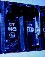
Photo 8.
Summary
UL 1995 – Heating and Cooling Equipment. (This standard covers central heating, central air-conditioning, and heat pumps.) UL 484 – Room Air Conditioners. These product safety standards detail the necessary safety tests and determine the required nameplate markings and instructions that are included by the manufacturer of the equipment. For example, paragraph 36.3(i) of UL 1995 specifies the equipment shall be marked with a “maximum overcurrent protective device size.” A typical nameplate will show the “MAXIMUM FUSE” and/or “MAXIMUM CIRCUIT BREAKER” size. If the nameplate specifies only fuses, then the unit is intended to be protected by fuses only. If the nameplate requires HACR (Heating, Air-Conditioning and Refrigeration) circuit breakers, then the circuit breaker protecting the unit must be marked “HACR.”
If the nameplate includes both fuses and HACR circuit breakers, as is the case of our nameplate example, then either is acceptable.
The selection process for hermetic motor-compressor circuit components is somewhat different from that of other motors. Using the markings on the end-use equipment helps ensure proper protection.


Find Us on Socials