Many electrical inspectors can tell you that confusion about wire temperature ratings and equipment termination temperature requirements results in their rejecting installations. Information about this topic can be found in the National Electrical Code (NEC), testing agency directories, product testing standards, and manufacturers’ literature, but many people do not consult these sources until it is too late.
Why are temperature ratings important?
Conductors carry a specific temperature rating based on the type of insulation used on the conductor. Common insulation types can be found in Table 310-13 of the NEC, and corresponding ampacities can be found in Table 310-16. Table 1 shows the ampacity of a 1/0 copper conductor based on different conductor insulation types.
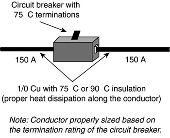
Figure 1. Based on the table, a 1/0 copper conductor is acceptable. The installation would be as shown in Figure 1, with proper heat dissipation at the termination as well as along the conductor length.
The ampacity of the 1/0 Cu conductor depends on the temperature rating of the insulation. At the same ampacity, a smaller conductor with higher-rated insulation can be used instead of a larger conductor with lower-rated insulation. As a result, the amount of copper and even the number of conduit runs needed for the job may be reduced.
One of the most common misapplications of conductor temperature ratings occurs when the established temperature rating of the equipment termination is ignored. This is particularly true for equipment rated for 600 V and less since the equipment is tested as a complete system using conductors sized by the NEC rules. Reduced conductor sizes result in the system having less ability to dissipate heat and therefore increase the operating temperature of the equipment terminations. Conductors must be sized by considering where they will terminate and how that termination is rated. If a termination is rated for 75°C, the maximum temperature at that termination is 75°C when the equipment is loaded to its ampacity. If 60°C insulated conductors are used in this example, the additional heat at the connection above 60°C could result in conductor insulation failure.
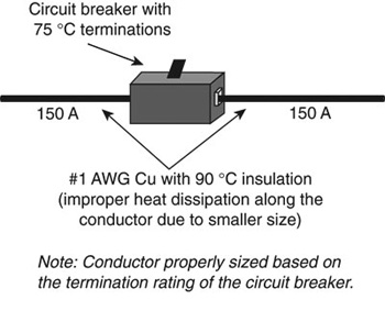
Figure 2. This may have led to overheating at the termination or premature opening of the overcurrent device due to the smaller conductor size
When a conductor is selected to carry a specific load, the user/installer or designer must know the termination ratings for the equipment in the circuit. For example, consider a circuit breaker with 75°C terminations and a 150A load. If a THHN (90°C) conductor is chosen for the job, review Table 310-16 in the NEC and look for a conductor that will carry the 150A. Although a 90°C conductor is being used, ampacity must be chosen from the 75°C column because the circuit breaker termination is rated at 75°C. Based on the table, a 1/0 copper conductor is acceptable. The installation would be as shown in Figure 1, with proper heat dissipation at the termination as well as along the conductor length. Had the temperature rating of the termination not been a consideration, a No.1 AWG conductor might have been chosen, based on the 90°C ampacity. This may have led to overheating at the termination or premature opening of the overcurrent device due to the smaller conductor size (see Figure 2).
In this same example, a conductor with a 75°C insulation type (THW, RHW, USE, etc.) also would be acceptable since the termination is rated at 75°C. A 60°C insulation type (TW) is not acceptable since the temperature at the termination could rise to a value greater than the insulation rating.
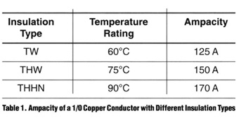
Table 1
The NEC Rules
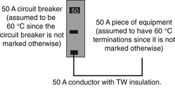
Figure 3. Conductors rated 60°C
Equipment Rated for 100A or Less— NEC 110-14(c)(1)(a) through (d)
NOTE: The equipment sizes and ampacities shown in the figures are arbitrary. The rules apply to any equipment rated 100A or less.
For equipment with termination provisions for circuits rated 100A or less or marked for No. 14 AWG through No. 1 AWG conductors, the NEC allows conductors to be used based on the following four conditions:
a. Conductors rated 60°C (see Figure 3).
b. Conductors with higher temperature ratings, provided the ampacity is determined based on the 60°C ampacity of the conductor (see Figure 4).
c. Conductors with higher temperature ratings, provided the equipment is listed and identified for use with such conductors (see Figure 5).
d. Conductors for specific motor applications (see Figure 6). This permission is specific to Design B, C, D, or E motors because those motors are temperature evaluated with conductors based on 75°C ampacity according to NEMA MG-2 (Safety Standard for Construction and Guide for Selection, Installation, and Use of Electric Motors and Generators).
Equipment Rated Above 100A—NEC 110-14(c)(2)(a) and (b)
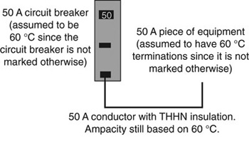
Figure 4. Conductors with higher temperature ratings, provided the ampacity is determined based on the 60°C ampacity of the conductor
For equipment with termination provisions for circuits rated above 100A or marked for conductors larger than No. 1 AWG, the NEC 110-14(c)(2)(a) and (b) allows conductors to be used based on the following conditions:
a. Conductors rated 75°C (see Figure 7).
b. Conductors with higher than 75°C ratings provided the conductor ampacity does not exceed the 75°C ampacity of the conductor size used (see Figure 8). This condition also permits the conductors to be used at ampacities higher than 75°C if the equipment is listed and identified for the higher rating. However, for equipment rated 600V and less, there is no listed equipment with termination ratings above 75°C.
The equipment termination ratings versus conductor insulation ratings are summarized in Table 2.
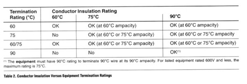
Table 2. The equipment termination ratings versus conductor insulation ratings are summarized in Table 2.
Caution on using lug ratings
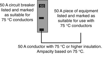
Figure 5. Conductors with higher temperature ratings, provided the equipment is listed and identified for use with such conductors
When terminations are inside equipment such as panelboards, motor control centers, switchboards, enclosed circuit breakers, safety switches, etc., follow the temperature rating identified on the equipment labeling instead of the rating of the lug itself. Manufacturers commonly use 90°C-rated lugs (i.e., marked AL9CU) on equipment rated only 60°C or 75°C. The use of the 90°C-rated lug in this type of equipment does not allow the installer to use 90°C wire at the 90°C ampacity. The Underwriters Laboratories® General Information on Electrical Equipment Directory states the following about terminations: “A 75°C or 90°C temperature marking on a terminal (e.g., AL7, CU7AL, AL7CU or AL9, CU9AL, AL9CU) does not in itself indicate that a 75°C or 90°C insulated wire can be used unless the equipment in which the terminals are installed is marked for 75°C or 90°C.”
Review the labeling of all devices and equipment for installation guidelines and possible restrictions.
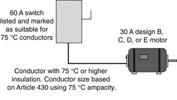
Figure 6. Conductors for specific motor applications
Available Equipment Terminations
Remember that a conductor has two ends, and that the termination on each end must be considered when applying the sizing rules. For example, consider a conductor wired to a 75°C termination on a circuit breaker at one end, and a 60°C termination on a receptacle at the other end. This circuit must be wired with a conductor that has an insulation rating of at least 75°C (due to the circuit breaker) and sized based on the ampacity of 60°C (due to the receptacle).
For electrical equipment rated for 600V and less, terminations are typically rated to 60°C, 75°C, or 60/75°C. No distributions or utilization equipment is listed and identified for the use of 90°C wire at its 90°C ampacity. This includes distribution equipment, wiring devices, and even utilization equipment such as HVAC, motors, and light fixtures. Installers and designers who have not realized this fact have equipment that does not comply with the National Electrical Code and that has been turned down by the electrical inspector.

Figure 7. Conductors rated 75°C
In equipment rated over 600V, the effect of the conductor as a heat sink is minimized, and ratings higher than 75°C are available. NEC 110-40 recognizes that conductors with sizes based on the 90°C ampacity can be used in installations over 600V.
An example of how 90°C wire might be used at its 90°C ampacity is shown in Figure 9. Note that the conductor does not terminate directly in the distribution equipment, but in a terminal or tap box using 90°C-rated terminations.
Frequently, manufacturers are asked when distribution equipment will be available with terminations that will permit 90°C conductors at the 90°C ampacity. This would require not only significant equipment redesign (to handle the additional heat), but also coordination of the downstream equipment where the other end of the conductor terminates. Significant changes in the product testing/listing standards also would have to occur.
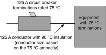
Figure 8. Conductors with higher than 75°C ratings provided the conductor ampacity does not exceed the 75°C ampacity of the conductor size used
A final note about equipment—some equipment requires the conductors that are terminated in the equipment to have an insulation rating of 90°C, but an ampacity based on 75°C or 60°C. This type of equipment might include 100 percent rated circuit breakers, fluorescent lighting fixtures, etc., and is marked to indicate such a requirement. Check with the manufacturer of the equipment to see if you need to take into account any special considerations.
What about higher-rated conductors and derating factors?
One advantage to conductors with higher insulation ratings is noted when derating factors are applied. This advantage is noted in the last sentence of NEC 110-14(c): “Conductors with temperature ratings higher than specified for terminations shall be permitted to be used for ampacity adjustment, correction, or both.” Derating factors may be required because of the number of conductors in a conduit, higher ambient temperatures, or internal design requirements for a facility. By beginning the derating process at the ampacity of the conductor based on the higher insulation value, you may not be required to upsize the conductor to compensate for the derating.
Remember these points while studying the derating process example:
- The ampacity value determined after applying the derating factors must be equal to or less than the ampacity of the conductor based on the temperature limitations at its terminations.
- The derated ampacity becomes the allowable ampacity of the conductor, and the conductor must be protected against overcurrent in accordance with this allowable ampacity.
Example of the derating process
Assume that you have a 480Y/277 Vac, 3-phase, 4-wire feeder circuit to a panelboard supplying 200A of noncontinuous fluorescent lighting load. Assume that the conductors will be in a 40°C ambient temperature and the conductors originate and terminate in equipment with 75°C terminations.
Additional information to consider from the NEC:
- Since the phase and neutral conductors all will be in the same conduit, consider the issue of conduit fill. NEC 310-15(b)(4)(c) states that the neutral must be considered to be a current-carrying conductor since a major portion of the load is a nonlinear load (electric discharge lighting).
- Based on this, four current-carrying conductors will be in the raceway. NEC 310-15(b)(2)(a) requires a 20% reduction in the conductor ampacity based on having four to six current-carrying conductors in the raceway.
- According to the ambient correction factors at the bottom of Table 310-16, an adjustment must be made of 0.88 for 75°C and 0.91 for 90°C.
Calculate, using a 75°C conductor such as THWN:
300 kcmil copper has a 75°C ampacity of 285A.
Using the factors noted earlier: 285A x 0.80 x 0.88 = 201A
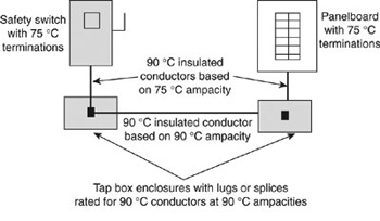
Figure 9. An example of how 90°C wire might be used at its 90°C ampacity
201A is now the allowable ampacity of the 300 kcmil copper conductor for this circuit. Had the derating factors for conduit fill and ambient not been required, a 3/0 copper conductor would have met the needs for this application.
Calculate, using a 90°C conductor such as THHN:
250 kcmil copper has a 90°C ampacity of 290A.
Using the factors noted earlier: 290A x 0.80 x 0.91 = 211A
211A is less than the 75°C ampacity of a 250 kcmil copper conductor (255A), so the 211A would now be the allowable ampacity of the 250 kcmil conductor. Had the calculation resulted in a number larger than the 75°C ampacity, the actual 75°C ampacity would have been used as the allowable ampacity of the conductor. This is critical since the terminations are rated at 75°C. Note that the conductor size was reduced by one size (300 kcmil to 250 kcmil) and still accommodated all of the required derating factors for the circuit. This is the primary advantage of using 90°C conductors.
Therefore, when using 90°C wire for derating purposes, you can begin derating at the 90°C ampacity. You must compare the result of the calculation to the ampacity of the conductor based on the termination rating (60°C or 75°C). The smaller of the two numbers then becomes the allowable ampacity of the conductor.
Summary
There are a number of factors that affect how the allowable ampacity of a conductor is determined. The key is not to treat the wire as a system in itself, but as a component of the total electrical system. The terminations, the equipment ratings, and the environment all affect the ampacity that can be assigned to the conductor. If the designer and installer keep each of the rules in mind, the installation will go more smoothly.