Article 411 was established during the 1996 National Electrical Code (NEC) cycle to provide a separate article for low-voltage lighting systems designed and listed as a complete system. The primary reason for Article 411 was the development of a new system of low-voltage incandescent spot lighting.
These new low-voltage incandescent spot lighting systems are installed using two insulated or uninsulated, exposed parallel conductors strung individually from one wall to another in an office or a home. Low-voltage luminaires are then connected between the two exposed individual conductors. The conductors are designed to support and provide power for the luminaires. This new system is seen as an alternative to installing tracking lighting while still providing the flexibility of initially locating or, in some cases, repositioning the luminaires along the supply conductors to highlight paintings or other areas of interest. These luminaires are also used to provide general illumination fo…r an area. Many lighting designers, electrical contractors, electrical engineers, and architects use this type of lighting in restaurants and high-end office buildings.
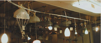
Photo 1. Low-voltage spot lighting
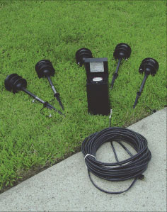
Photo 2. Power suppy, cable, and luminaires
The Standard for Luminaires, UL 1598, covers safety requirements for luminaries, however, low-voltage lighting systems are covered by specific safety standards for the low-voltage aspects of these systems. The Standard for Low Voltage Landscape Lighting Systems, UL 1838, covers the safety requirements for landscape lighting systems; the Standard for Low Voltage Lighting Systems, UL 2108, covers incandescent luminaires and luminaire fittings; and the Standard for Low Voltage Lighting Systems for Use in Recreational Vehicles, UL 234, covers luminaires for recreational vehicles. The Standard for Portable Electric Luminaires, UL 153, covers luminaires with specific requirements for low-voltage lighting systems intended for installation under a shelf, a cabinet or a similar structure. When the low-voltage lighting system is being installed in permanent cabinets with a remote power source connected to fixed wiring, these products are required to comply with UL 2108 for low-voltage incandescent luminaires and luminaire fittings.
This article will provide general information on all low-voltage lighting systems. However, the article will focus specifically on low-voltage landscape lighting systems.
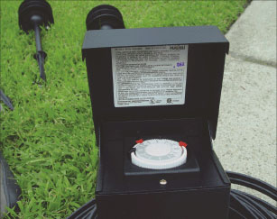
Photo 3. Power supply
A low-voltage lighting system primarily includes a power supply, a flexible cord to supply power to the luminaires, wire and device connectors, and any associated components necessary for completion of the system. The power supply can utilize a cord-and-plug connection to a receptacle or a permanent connection to conduit, nonmetallic-sheathed cable (Type NM cable), or other NEC chapter 3 wiring methods depending upon the specific product standard and compliance with Article 411.
Since low-voltage lighting systems are required to be listed, NEC 110.3(B) requires the listing and labeling instructions, as well as the markings, ratings, and installation instructions be followed. The ratings and markings on the power supply, as well as the installation instructions, will limit the number of individual low-voltage branches or circuits that can be supplied by the power supply.
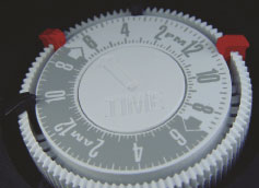
Photo 4. Time clock dial
Any number of individual branches can be supplied from the power supply or transformer depending upon the design of the system, but the total wattage of the luminaires on all the branches cannot exceed the rating of the transformer or power supply. The rating of the power supply will determine the overall number and wattage of the luminaires that can be fed from each branch of the power supply. NEC 411.2 provides the definition for low-voltage lighting systems and states that one or more power supply secondary low-voltage circuits are permissible but each circuit is limited to 25 amperes maximum with a maximum voltage of 30 volts, ac or dc.
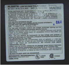
Photo 5. Label with maximum ratings
NEC 411.2 also provides basic information on the method of converting line voltage to low voltage for these low-voltage systems. Low-voltage lighting systems can have a maximum voltage of 30 volts ac or dc with a peak voltage that cannot exceed 42.4 volts under any load conditions. The 30 volts in the definition in 411.2 is an RMS (Root Means Squared) value that can be exceeded only by an instantaneous peak of 42.4 volts.
Single tap transformers are not usually an issue, except where the transformer primary voltage is excessive and, under a light load, the secondary voltage exceeds the 42.4-volt peak. Testing in 1950s determined that a shock and let-go value of not greater than 42.4 volts was an acceptable level in most dry locations and would not be lethal to a person in contact with the circuit. This value of 42.4 volts peak would not be acceptable in a wet location since the resistance of a person’s body would be much lower in a wet condition.
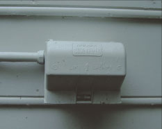
Photo 6. Weatherproof receptacle cover
Even though Tables 11(A) and 11(B) in chapter 9 apply to Class 2 and Class 3 power supplies and not specifically to low-voltage lighting systems, these tables can provide direction and information for acceptable ac and dc voltage levels for both dry and wet locations.
A non-sinusoidal peak voltage of 42.4 volts for an ac circuit is considered a safe voltage under dry conditions and would not normally constitute a shock or fire hazard. In wet conditions, this voltage must be limited to 15 volts for a sinusoidal ac and 21.2 volts peak for a non-sinusoidal ac. Since the body’s resistance is decreased by water, the permissible voltage of the output of the low-voltage system is decreased accordingly to ensure safe handling and operation of these circuits where water is a concern. Using low-voltage systems in close proximity to or in fountains and swimming pools should only be considered when all the NEC requirements are applied.
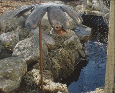
Photo 7. Luminaire in fountain area
For dc circuits, there are two conditions possible, a pulsating dc circuit or a non-pulsating dc circuit. With pulsating dc, where the rate is 10 to 200 hertz, the maximum safe voltage in a dry location is considered to be 24.8 volts peak. Pulsating dc can occur for a number of reasons but the most common reason is the design and lack of filtering of the dc power supply. Pulsating dc at these low frequencies can have an affect on the human body by disrupting the electrical signals to muscles and other organs. Where water may be present but direct immersion is not an issue, the voltage level is a maximum 30 volts for non-pulsating dc and 12.4 volts peak for pulsating dc in the 10 to 200 hertz range.
Remember, as the load increases, the voltage of a system will often sag affecting the operation or brightness of the lamps within the luminaires. When a heavy load is removed, the voltage goes back up so care must be taken to never exceed the 42.4-volt peak on the secondary of the transformer. Multiple tap primary or secondary transformers must not develop more than 30 volts or 42.4 volts on the secondary, even in its most lightly loaded condition.
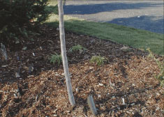
Photo 8. Low-voltage landscape lighting
Furthermore, NEC Sections 411.5(A) and 250.22(4) do not permit the secondary of a low-voltage lighting system transformer to be grounded for any reason. The ungrounded secondary in conjunction with the impedance between the primary and the secondary of the transformer help ensure a low potential fault level. Also, by using an isolation power supply, it is less likely that a short will occur from the primary to the secondary side of the power supply.
NEC 411.5(B) requires an isolation transformer for any low-voltage lighting system. An autotransformer is not acceptable since the primary and secondary of an autotransformer are not isolated. For example, a transformer with a 120-volt primary must be isolated from the 30-volt secondary. An autotransformer connected in a buck configuration (the windings connected together as subtractive rather than additive) would not be an acceptable conversion from line voltage to low voltage for these lighting systems. By using an isolation power supply, safety will be maintained by assuring that a voltage not greater than 30 volts will be supplied to the lighting system.
Low-Voltage Landscape Lighting Systems
Photo 9. Low-voltage landscape lighting
Even though new NEC Article 411 was developed to cover the new low-voltage track lighting, low-voltage landscape lighting is also covered by default since they are designed and listed systems. A low-voltage landscape lighting system consists of a power unit, a number of lighting units (luminaires), cable and luminaire connectors, and interconnecting cable. Individual listed components from the same company or from different companies may be used to form the complete system, if all the components have been investigated, tested, and listed as a complete system.
These systems commonly use a transformer or power supply to convert 120 volts from an outdoor receptacle outlet to a lower voltage at the secondary of the power supply. A 20-ampere branch circuit is the highest rated branch circuit that can supply the primary of the low-voltage power supply. The maximum permissible output of each secondary circuit, based upon the applicable safety standard, is 15 volts ac and 25 amperes at 300 volts. The power supply can provide multiple secondary circuits but each secondary circuit can only be 25 amps with a maximum of 300 watts. The maximum number of lighting units that can be connected to the secondary of the power supply is based on the wattage of the lamps.
The transformer or power supply usually has a built-in time clock to allow the system to be turned “on” and “off” at a preset time. A photocell may be designed into the power supply unit to sense “”daylight”” and ensure that the lighting would not be “”on”” during daylight hours. If this function is desired, purchase a power supply where the photocell is an integral part since installing an external photocell between the 120-volt supply and the power supply will affect the time clock function by not holding continuous power to the clock motor.
As noted above, low-voltage lighting components must be used in accordance with the product ratings, markings, and instructions. For example, the power supply (transformer) unit may be marked with an input rating of 120 volts, 60 hertz, 3 amps with the output rated at 12 volts and 300 watts. The transformer is a 10 to 1 ratio transformer with a maximum secondary wattage of 300 watts at 12 volts. The total wattage of the lamps installed on this power supply cannot exceed 300 watts. Depending upon the wattage of the lamps, there could be 12 lamps at 25 watts each or 15 lamps at 20 watts each, for a total of 300 watts, or any other similar combination.
The maximum secondary amperage for this particular power supply would be 300 watts divided by 12 volts = 25 amps. This value conforms to the maximum amperage of 25 amps per circuit found in the definition of lighting systems operating at 30 volts or less in 411.2. Larger power supplies could supply multiple secondary circuits but each secondary circuit cannot exceed 25 amps at 300 watts.
Power units marked as “”Indoor Use Only”” can be used only in indoor applications and are not to be installed in damp or wet locations. These indoor units are manufactured with secondary input connections that are compatible with wiring methods from NEC chapter 3, such as those that include ½ inch knockouts or NM cable clamp, permitting compliance with 411.4. Section 411.4 states that low-voltage lighting systems must not be concealed or the wiring must not extend through a building wall, unless using a wiring method specified in chapter 3. The power supply cannot be installed in a concealed location behind drywall or where access is rendered inaccessible without damaging or destroying the building finish. Likewise, low-voltage cable is not a wiring method that can be buried in a wall, a ceiling or a floor. Armored cable (Type AC cable), metal-clad cable (Type MC cable), nonmetallic-sheathed cable (Type NM cable), and raceways of various types, where permissible in their specific articles, are acceptable as a wiring method from the secondary of the power supply through walls, floors, and ceilings.
There is a change that has been accepted for the 2005 NEC that will relax the requirements in 411.4 by permitting Class 2 wiring methods to be used and concealed within walls, floors, and ceilings where the power supply is a listed Class 2 power supply and the wiring is installed in accordance with 725.52. There may be a drawback to this new permissive rule that should be considered. Tables 11(A) and 11(B) in chapter 9 do not permit a Class 2 power supply to have nameplate wattage that exceeds 100 VA or amperage that exceeds 5 amps at 30 volts or less. Comparing this 5-ampere value to the 25-ampere and higher wattage permission granted in Article 411 for low-voltage lighting systems will severely restrict the use of Class 2 power units. Class 2 power supplies will, however, provide an alternative cable that can be installed inside walls, ceilings, floors, cabinets, and other spaces where chapter 3 wiring methods were not easily installed.
Power supplies marked as “Outdoor/Indoor Use” can be used for either indoor or outdoor applications and are also designed for chapter 3 connections at the secondary side of the power supply. These units must follow all of the same requirements for an indoor unit but may be installed in a damp or wet location. These multiple application power supplies have passed all of the additional tests for an outdoor device.
Power supplies marked as “Outdoor Use Only” cannot be installed indoors and are designed to have a cord-and-plug connection to an outdoor receptacle outlet with a cover assembly marked suitable for wet locations and in compliance with Article 406 of the 2002 NEC. Section 406.8(B)(1) requires any 15- or 20-ampere outdoor receptacles installed outdoors in a wet location to have a cover that is waterproof, whether or not the attachment plug is inserted. This feature keeps water out of the cover and away from the receptacle, especially where attachment plugs will be inserted for long periods of time in outdoor applications. Landscape lighting is specifically referred to in 406.8(B)(2)(a) for all receptacles located in a wet location.
The wire used to connect the power unit to individual luminaires and lighting fittings must be listed SPT-3, Underground Low Energy Circuit, cable, or any other wire or cable suitable for direct burial. Any wire or cable used for this application, including SPT-3 cable, must be listed for wet locations and must be sunlight resistant (ultraviolet light protected). While most installers use the listed SPT-3 cable, there may be circumstances where a different cable would be installed. For example, most cable shipped with low-voltage lighting systems is 16 through 12 AWG (American Wire Gauge), depending upon the anticipated load of each circuit and the size of the power supply. Size 16 AWG can typically be used for runs up to 100 feet with only minimal voltage drop, 14 AWG is good up to 150 feet, and 12 AWG is recommended for runs up to 200 feet. Excessive voltage drop is critical to the proper operation of the luminaires and the length of run may require larger wire than 12 AWG to ensure proper voltage to the lighting units.
If larger wire is necessary to counter voltage drop in long runs, Type UF (Underground Feeder and Branch circuit) cable could be used. Another method would be to start a long run with 12 AWG SPT-3 cable and then convert to 16 AWG or 14 AWG in the middle or toward the end of the run. Limiting the number and size of lamps on the long run will also provide a solution for excessive voltage drop. The following formula will help determine the voltage drop in your circuit: 2 X length of run X ampacity of load X the resistance of the wire in thousand feet (that value can be found in Table 8 of chapter 9 using the uncoated wire column) divided by 1000 feet = voltage drop.
One of the most common Code violations encountered when inspecting low-voltage landscape lighting systems is the burial depth of the cable. These direct burial cables are subject to the burial depth required by 300.5(A) and accompanying Table 300.5, as well as the burial depth noted in the installation instructions for the lighting system. In column 5 of Table 300.5, circuits for landscape lighting, limited to not more than 30 volts, and installed with Type UF or other identified cable must be at least 6 inches deep, except for outdoor parking areas and driveways. Cables located under residential driveways and outdoor parking areas must be at least 18 inches deep. The purpose of the increased depth is to ensure that earth movement from heavy vehicular traffic will not damage the cable. Individual cables from the low-voltage luminaires are connected to the branch cable at 6 inches or 18 inches deep and then are routed into the luminaire. Most installers ignore the cable depth rule or are not even aware that it exists. Installation instructions and the NEC provide the burial depth and this minimum depth must be followed.
Another frequent violation occurs around swimming pools, spas, fountains and similar areas. NEC 411.4(2) does not permit low-voltage lighting systems within 10 feet of these areas, unless permitted by Article 680. Section 680.22(B) covers area lighting around a pool. Any luminaire installed within 5 feet horizontally of the pool edge must be located at least 12 feet above the maximum water level of the pool. There are many existing low-voltage lighting installations installed after the pool installation inspection has occurred where the luminaires are installed within 3 to 5 feet of the water’s edge at or near ground level, which clearly is a violation.
Section 680.22(B)(4) permits luminaires to be installed within 5 to 10 feet horizontally of the pool’s edge only where a ground-fault circuit interrupter (GFCI) protects the luminaires. Since low-voltage landscape luminaires are supplied by a low-voltage power supply, such as a transformer, providing GFCI protection on the primary side of an isolation transformer will not provide GFCI protection on the secondary side. GFCI devices will not operate at the 15-volts or less supplied by the secondary of the power supply. This leaves only two options: one is to locate all low-voltage landscape lighting at least 10 feet from the pool or fountain edge; or, two, to use a special power supply.
There are low-voltage lighting power units that are marked “For Use with Submersible Fixtures or Submersible Pumps.” In this case, a special transformer is used that complies with the requirements in 680.23 for underwater luminaires installed below the normal water level of the pool. This transformer is specifically listed for this use and is an isolated winding type transformer with an ungrounded secondary similar to the low-voltage landscape lighting transformer, as required by 411.5(B). The low-voltage pool lighting transformer has one additional feature in its design. It has a grounded metal barrier or shield between the primary and the secondary. This metal barrier or shield prevents a direct internal short between the primary and the secondary of the transformer. If a short does occur on the primary side, it will short to the metal shield and the primary overcurrent protective device will operate. If a short develops on the secondary side to the shield, the secondary overcurrent protective device, if provided, will operate. If there isn’t a secondary overcurrent protective device and the primary is providing protection through the transformer, the primary device should operate.
As you can see, installing low-voltage lighting systems is relatively simple, if a few simple NEC rules are followed. The result of a properly installed system is a beautifully illuminated landscape and a safe installation.