Electrical Shock
An estimated 58 people lose their life each week as a result of electric shock.
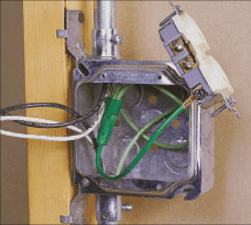
Photo 1. Proper grounding
In an electrical system, the grounding and bonding system is the primary protection against electrical shock hazards. It provides a low resistance path to ground to protect against electrical faults. The effective ground-fault current path ensures facilitation of overcurrent device operation under ground-fault conditions. The earth is not to be considered as an effective ground-fault current path [see 250.4(A)(5)]. Using proper grounding and bonding techniques, testing and maintaining a good electrical ground and installing protection devices are the best ways to protect people and equipment from electrical shock.
Proper Grounding Techniques
Maintaining a good quality equipment grounding system starts with wiring the circuits correctly. The NEC requires that the removal of any device cannot interrupt the grounding path, in accordance with 250.148(B). Receptacle manufacturers have responded by supplying receptacles with only a single grounding connection. This would prohibit electricians from wiring the device in series with the grounding circuit.
Pigtail Connections
A common method of ensuring that the equipment grounding connection remains intact is through the use of a pigtail connection. The Code term for this “”pigtail”” is equipment bonding jumper which is defined in Article 100. To make a pigtail connection, take both ground wires and join them with a 6-inch wire of the same color that has been stripped on either end. Hold all three tightly and bind them together with a wire connector. Be sure to use the right size connector for the size and number of wires.
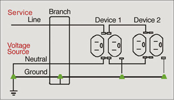
Figure 1. Receptacles with a single grounding connection
Special connectors are available to make this job easier. With one, a bare copper wire is inserted through a hole at the top of the connector. All the wires are then bound together, by twisting the connector until tight.
Pre-made pigtails are becoming popular because of the timesaving involved. For example, some connectors now combine a twist-on wire connector with a pre-crimped pigtail. The ultra-flexible, six-inch lead provides hassle-free positioning in a junction box, and the grounding pigtails come with a pre-crimped fork connection for quick and easy installation of the device.
Bonding the Junction Box to the Grounding Conductor
In many wiring circuits, more than one equipment grounding conductor enters an outlet box. According to NEC 250.148, where more than one equipment grounding conductor enters a box, all such conductors shall be spliced or joined within the box or to the box.
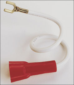
Photo 2. Pigtail connector
The only exception is for isolated receptacles, covered in Section 250.146(D) where isolated receptacles are required for the reduction of electrical noise (electromagnetic interference).
For metal junction boxes, the grounding conductors from each device also needs to be connected to the box with a listed grounding device, or a grounding screw, that is not used for any other purpose.
Bonding the Receptacle Grounding Terminal to the Junction Box
A device may have to be bonded to the junction box with a jumper. According to NEC 250.146, an equipment bonding jumper shall be used to connect the grounding terminal of a grounding-type receptacle to a grounded box unless grounded as in 250.146(A) through (D).
(A) Where the box is mounted on the surface, direct metal-to-metal contact between the device yoke and the box or contact device that complies with 250.146(B) shall be permitted to ground the receptacle to the box. At least one of the insulating washers shall be removed from receptacles that do not have a contact yoke or device that complies with 250.146(B) to ensure direct metal-to-metal contact. This provision does not apply to cover-mounted receptacles unless the box and cover combination have been listed as providing an acceptable ground continuity between the box and receptacle.
(B) Contact devices or yokes designed and listed as self-grounding. shall be permitted in conjunction with the supporting screws to establish the grounding circuit between the device yoke and flush-type boxes.
(C) Floor boxes designed for and listed as providing satisfactory ground continuity between the box and the device.
(D) Where required for the reduction of electrical noise (electromagnetic interference) on the grounding circuit, a receptacle in which the grounding terminal is purposely insulated from the receptacle mounting means shall be permitted. The receptacle grounding terminal shall be grounded by an insulated equipment grounding conductor run with the circuit conductors. This grounding conductor shall be permitted to pass through one or more panelboards without connection to the panelboard grounding terminal as permitted in 408.40, Exception, so as to terminate within the same building or structure directly at an equipment grounding terminal of the applicable derived system or service.
The receptacle grounding terminal is connected to an insulated equipment grounding conductor that is run with the circuit conductors and is permitted to pass through one or more sub-panels without connection to the panelboard grounding terminal bar as permitted in Section 408.40 Exception.
Note that the use of an isolated equipment grounding conductor does not relieve the requirement for grounding the raceway system and junction box.
Maintaining an Effective Grounding Path
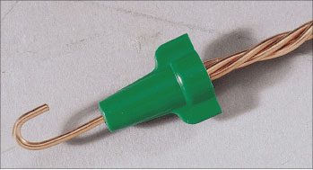
Photo 3. Pigtail connector (lead to device is shortened for the photo).
A good electrical grounding system involves more than following a few NEC requirements; it must also be an effective grounding system. The path to ground is the system grounded conductor and equipment connection to the earth and serves as a path for stray current. If electricity follows the path of least resistance, then the grounding circuit (path) must have a lower resistance than an individual to protect them. The rule of thumb for protecting people is to maintain a ground impedance of less than one ohm. Note the Code has no set value for this resistance other than for the maximum resistance values indicated for rod, pipe, or plate electrodes, which is 25 ohms.
False Grounds
The grounded (often a neutral) conductor can generally be connected to the ground only at the service disconnecting means neutral bus [see 250.24(A)(5) and 250.142(B)]. The main bonding jumper at the service connects the grounded conductor and equipment grounding conductor together at that point. The main bonding jumper serves as a vital link in the ground-fault current path from the service disconnect to the source windings (usually a utility transformer). . Sometimes through error or ignorance, the grounded (neutral) conductor and equipment grounding conductor are connected together on the load side of the service disconnecting means which violates the general requirements of 250.24(A)(5). This is often referred to as a false or bootleg ground and can create unwanted or objectionable current in the grounding circuit. If the grounded conductor and equipment grounding conductors are connected anywhere else in the building, all grounded metal can become part of the grounded (neutral) conductor return circuit for unbalanced neutral current that can create various voltage potentials on electronic equipment. When using common receptacle testers, this condition typically shows up as normally wired.
Earth Ground
The path to ground extends beyond the main panel to the earth ground system known as the grounding electrode system as covered by Section 250.50. The earth ground could be a single ground rod, multiple ground rods, a mat or a grid system, or various other conducting elements that establish a connection to the earth. The Code requires that if present, all items listed in 250.52(A)(1) through (6) be bonded together to form the grounding electrode system. There is one exception for concrete-encased electrodes but this applies only to footings of existing buildings or structures. Section 250.56 addresses ground resistance by indicating that if the grounding electrode (rod, pipe, or plate type) does not have a resistance to ground of 25 ohms or less, an additional electrode of any of the types listed in 250.52(A)(2) through (7) must be added and installed at least 1.8 m (6 ft) from the first electrode. The grounding electrode system can be tested with an earth resistance tester, or a ground resistance clamp meter.
While testing the resistance of the ground electrode of the rod, pipe, or plate types after installation will satisfy NEC requirements in 250.56, it is not always enough to ensure protection of personnel or electronic equipment.

Photo 4. Ground resistance clamp meter
The resistance of the ground electrode is heavily dependant on the amount of soil resistivity. Because soil resistivity relates to moisture and temperature, the resistance of the grounding system will vary throughout the different seasons of the year. To ensure an effective grounding electrode system, include the ground electrode or earth ground as part of your standard testing procedures in your facility. A ground resistance clamp meter enables electricians to measure the resistance of the ground electrode in a fraction of the time required using the traditional three-point fall of potential test.
Ground-Fault Circuit Interrupters
The Code requires the installation of ground-fault circuit interrupters (GFCIs) in residential dwellings to protect against shock. Receptacles in bathrooms, garages, outdoors, crawl spaces, unfinished basements, kitchens, near wet bar sinks, utility sinks and laundry sinks require protection. All 125-volt 15- and 20-ampere receptacles at boathouses are required to be GFCI as well as any branch-circuit outlet for a dwelling unit boat hoist (see 210.8(A) for additional information). The Code also requires GFCI protection for many installations in other than dwelling units. [See 210.8(B) for a more complete list of those areas where this ground-fault circuit interrupter protection is required].
A GFCI receptacle is a device with a built-in circuit to detect leakage current to ground on the load side of the device. When the GFCI detects leakage current in the 4–6 milliampere range, it will interrupt power to the load side of the device, preventing a hazardous ground-fault condition. [See the definition of ground-fault circuit interrupter (GFCI) Class A GFCI device in Article 100 for additional information].
These devices should be tested regularly, because they rely on mechanical connections that can degrade over time. According to a recent study performed by the Leviton Institute, on average 15 percent of GFCIs were inoperative when tested. “Voltage surges from lightning, utility switching and other sources all take their toll on the devices, which is why Underwriters Laboratories (UL) requires that GFCIs be tested monthly.”
Equipment Failure
When sensitive electronic equipment fails, the initial reaction is to throw our hands up and blame it on poor power quality. This makes the problem seem unmanageable and out of our control. Most of these problems are actually under our control, because 80 percent of all power quality problems are found in the electrical distribution and grounding and bonding system.
In addition to preventing the possibility of fire, a good low-impedance electrical grounding and bonding system will serve to protect electronic equipment. A high-resistance connection, like a loose wire, will cause the voltage to fluctuate, or drop, when a large load is applied. If the voltage drops low enough, it can cause electronic equipment to lock up, reset or shut down completely. Grounding is another concern for electronic equipment. While ground impedance of one ohm or less may protect people from electric shock, it may not be adequate protection for electronic equipment. IEEE recommends a ground impedance to be less than 0.25 ohms for proper protection.
Isolated Grounds and Dedicated Circuits
In some cases, it is easier to isolate sensitive electronic equipment than to re-wire an entire circuit. This can be done by running an isolated ground for the equipment in question, or by running a new dedicated circuit. The Code does not currently include the term, dedicated circuit; however, the term individual branch circuit is defined; and such a circuit is often installed for sensitive electronic equipment. Individual branch circuits can also include isolated grounding conductors installed to meet the provisions of 250.146(D).
An isolated ground protects the equipment from other equipment on the same grounding circuit. Electronic equipment can create electrical noise on the grounding circuit, which can interfere with the operation of other equipment on the circuit. It is important to note that an isolated ground will not protect equipment from harmonic distortion running through a shared neutral conductor of typical multiwire branch circuits.
In some cases, running a dedicated circuit (individual branch circuit) is necessary to completely isolate a piece of equipment in order to ensure protection.
Article 285 provides the rules and covers the use of transient voltage surge suppressors. These devices protect power, telephone and cable lines from transient voltage. Transients are short high amplitude pulses caused by a release of energy onto the electrical system. These pulses of energy can be caused by internal sources, such as a capacitor releasing energy into the system, or external sources like lighting.
Conclusion
The hidden dangers associated with branch-circuit wiring are very serious, but fortunately the precautions are straightforward. We can protect ourselves and equipment by using certified devices and testing equipment from reputable manufacturers and by implementing policies on branch-circuit testing. These policies should include verifying proper wiring, testing devices, checking the integrity of the branch circuit, and measuring the integrity of the grounding system.
Installers should always check all devices immediately after installation to verify proper wiring and test devices. It is generally not the responsibility of the electrical inspector to test installations upon completion. The installing contractor is generally responsible for this type of testing. Receptacles should be checked to avoid common wiring errors, such as reversed polarity or an open neutral. Checking the voltage level with a voltage tester quickly verifies that the receptacle has been correctly wired for either 120 or 220VAC. Checking continuity across a switch verifies that it working correctly. A variety of testers are available on the market to test these devices quickly and accurately.
Test electrical circuits under load to test the integrity of the branch circuit. The voltage drop test can identify high resistance connections, which can lead to fires, breakdown in insulation, and poor efficiency of the electrical system, which can contribute to erratic equipment operation.
Test the integrity of the grounding system, which includes not only the equipment grounding conductors, but also the ground rod or grounding electrode system. A low- impedance path on both of these systems is essential to protect against electrical shock. The effective ground fault current path ensures that overcurrent devices will operate under ground fault conditions. See 250.4(A)(5).
In summary branch-circuit testing is an important part of wiring any circuit. It verifies that devices have been wired up correctly and allows you to protect yourself against the hidden defects in an electrical system.