What Is a VFD?
A variable frequency drive (VFD) is an electrical device we use to control the speed of a standard three-phase ac induction motor. The number of poles designed into a motor and the frequency applied to the motor determine the motor base speed. We can conveniently adjust the speed of a motor by changing the frequency applied to the motor. You could adjust motor speed by adjusting the number of poles, but this is a physical change to the motor. It would require rewinding, and would result in a step change in the motor’s base speed. So, for convenience, cost-efficiency, and precision, we change the frequency (and voltage). At any given frequency output of the drive, you get a new torque / speed curve from the ac motor.
Saving Energy with Variable Frequency Drives
It is estimated that over 60 percent of the electrical power generated in the U.S. is used to power fans and pumps. Most fans and pumps are of the centrifugal design type. Centrifugal fans and pumps follow the Affinity Laws of pressure, flow and energy consumed.
The Affinity Laws (also called the Fan Laws) state that fan output CFM or flow is directly proportional to the speed of the fan. Static pressure is proportional to the fan speed squared, and fan required HP is proportional to the fan speed cubed. Therefore, according to the Affinity Laws of speed, pressure, and horsepower, to produce 50% airflow, the fan would be run at 50% speed. At this operating point, the fan would produce 25% of rated pressure (0.5 x 0.5 = 0.25), and would require only 12.5% of rated horsepower (0.5 x 0.5 x 0.5 = 0.125 or 12.5%).
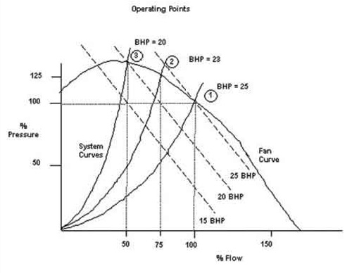
Figure 1
There are several methods of obtaining variable air flow from a centrifugal fan. The most common methods used are outlet dampers, inlet guide vanes and variable speed drives. We will use figure 1to illustrate the difference in energy consumed between outlet damper and variable speed flow control. The top curve in the figure is the fan curve. The fan curve represents the pressure and flow-producing characteristics of a given fan. The curves rising from the origin of the X and Y axis are the system curves. The system curves represent the physical air distribution system including the ductwork, filters, balancing dampers, and the fan outlet flow control damper mechanism.
In figure 1, point 1 represents full or design flow with the outlet damper in the full open position. In the example shown, this corresponds to approximately 25-brake horsepower (BHP) in energy required to deliver 100% flow at 100% rated pressure. Point 2 represents a 75% flow condition with the outlet damper partially closed. Due to pressure loss across the outlet damper, the pressure downstream of the damper decreases. This pressure/flow condition corresponds to approximately 23 BHP of energy required. Finally, point 3 represents a 50% flow condition by further closing of the outlet control damper with the corresponding flow decrease and increasing head across the nearly fully closed damper. This pressure/flow condition corresponds to approximately 20 BHP of energy required.
This control method is sometimes referred to as “riding the fan curve.” As shown in figure 1, outlet damper control and riding the fan curve result in a small reduction in BHP at the reduced flow rates. We are supplying energy (kW) to the fan motor to develop pressure, only to bleed the pressure off with a head drop across the restricting outlet damper. This method of control can be compared to driving a vehicle with one foot on the accelerator and the other foot on the brake. To slow the speed of your vehicle, one applies more brake and leaves the throttle wide open, rather than lifting off the throttle!
VFDs Avoid Traditional Brake Control; Provide Optimal Energy Usage
A much more efficient system would employ a VFD to operate the fan motor. In a VFD system, the speed of the fan motor is reduced, thereby reducing the amount of airflow. Simply locking the outlet dampers at fully open position and supplying a VFD can retrofit an outlet damper system to a variable speed system.
The electrical signal that was used to control the damper position can now be used as the speed reference signal for the VFD. With variable speed operation, each speed creates a new, different fan curve. Running a fan at reduced speed produces a new fan curve roughly parallel to the full-speed design curve (figure 2).
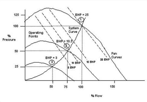
Figure 2
With VFD fan control, if 75% airflow is required (point 2), as in the previous example, the drive would run the motor at 75% speed. From figure 2, one can see that the point 2, 75% flow rate now requires only 10.5 BHP. Similarly, for the 50% flow condition, using variable speed control now requires approximately 3 BHP. With outlet damper control, the same operating condition required approximately 20 BHP!
To put these potential savings into perspective, we will assume the following operating conditions for the example 25-HP fan above. Assume this is a hospital supply fan application and therefore this fan runs 24 hours per day, 7 days per week, 365 days per year or 8760 annual hours of operation. We will further assume a standard bell curve duty cycle of reduced flow operation as follows: 100% flow for 2.5% time; 90% flow for 7.5% time; 80% flow for 10% time; 70% flow for 15% time; 60% flow for 22% time; 50% flow for 22% time; and 40% flow for 21% of the 8760 total hours.
Using the Affinity Laws and the above assumptions results in the following required kWHs (kilowatt hours) per year for constant speed, outlet damper control—171,975 kWHs per year. With the same assumptions and variable speed fan control, the fan would require only 53,430 kWHs per year. Finally, assuming that this hospital pays an average of $0.10 USD per kWh (including basic kW rate and demand charges), the outlet damper control method would require $17,198 USD per year to operate the supply fan. VFD control would require $5,343 USD per year for the same flow/operation of the supply fan. Total savings would therefore be $11,855 USD per year for this example application.
Even with very liberal estimates for VFD first cost and installation costs, the above example would lead to less than one-year payback. While rules of thumb are always dangerous, in the author’s opinion, with typical/prevailing U.S. electrical energy costs, most centrifugal fan and pump applications above 10 HP will have a two-year or less payback. Figure 3 shows in graphical form the amount of energy savings (reduced power consumption) that can be realized using a VFD.
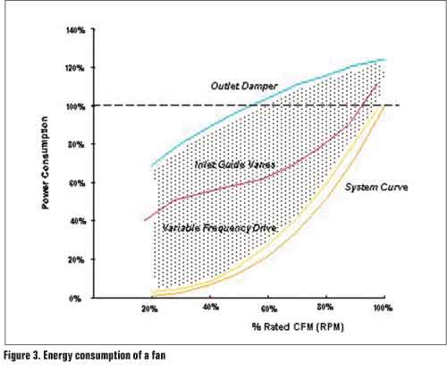
Figure 3
How to Spot a Good VFD Potential Application
Since hospitals are typically a 24/7 operation, most fan and pump applications in hospitals are potential variable speed candidates. Simply stated, any HVAC system that spends a large amount of its total operating hours at less than peak load is a potential candidate for VFD retrofit.
One easy method for discovering variable speed opportunities is a fairly simple, walk-around-type inspection. Each time you are in a mechanical room, note the position of the outlet damper or inlet guide vane damper actuator. If the actuator is usually substantially closed, this is probably a good candidate (figure 3). A similar inspection could be accomplished on the pumps in the facility. If the pumps use throttling or bypass valves, note the position of their associated valves. Once again, if the valves are partially closed most of the time, this is probably a good retrofit candidate.
Of course, there are more sophisticated ways for spotting potential retrofit candidates such as taking flow and power measurements and comparing these figures to the rated flow and power of the system under study. Also, there are many independent companies that will perform energy savings estimates for facility managers.
Potential hospital fan and pump VFD applications include supply and return fans; fan coil units; DX units; exhaust fans; cooling tower fans; liquid coolers; condenser fans; secondary chilled water pumps; and domestic and hot water pumps. In addition, there is a growing trend of applying VFDs on primary chilled water and condenser water pumps. In short, any fan or pump in the hospital is a potential candidate for variable speed control.
Other Important VFD Benefits
In addition to energy savings, VFDs provide other benefits to the electrical systems they reside upon and the mechanical equipment they control. For example, when an ac motor is “line started” on utility power, it will require 600 to 800% of its rated current (inrush current) while it is accelerating. An ac motor started by a VFD will be limited to 110% inrush current worst case. In addition, PWM VFDs will dramatically increase power factor seen by the utility. A fan using outlet dampers at 40% flow may have a motor true power factor of 40% or less. With the same motor on VFD power at the same 40% flow, the utility would typically see an 80% or better true power factor.
From a mechanical benefit standpoint, bearings run at reduced speeds typically last much longer than their full speed counterparts. Also, drives inherently “soft start” the driven mechanical equipment. This soft start extends not only the life of the motor and bearings, but also drastically reduces belt wear and tear. Cooling tower gear boxes that are stressed by across-the-line utility starting will experience much less wear and tear when soft started with a VFD. Also, cooling tower “short cycling” will be avoided by VFD control, further extending the life of the gear box. Finally, the mechanical linkages controlling outlet dampers, inlet guide vanes or throttling valves require routine maintenance and are prone to stick or fail. Many VFDs have been installed on in-flight vane axial control fans simply to eliminate the complex mechanical linkages—and their associated high maintenance costs—with these types of flow control.
While these mechanical and electrical side-effect benefits of VFD control are many, they are often ignored because they are harder to quantify from a dollar and cents standpoint than the kWh savings which can be dramatic and easily measured. However, these side-effects are real and can often save as much as the efficiency improvement savings.
Other Important VFD Application Considerations
The need for controlling the level of harmonic current in power distribution systems is widely recognized as an important factor in selecting and applying adjustable speed drives and other non-linear load equipment. With the large amount of possibly sensitive, electronic life safety equipment prevalent in the modern hospital environment, administrators should be aware of possible harmonic and EMI/RFI noise implications.
IEEE Standard 519-1992 explains the reasons for limiting harmonics and recommends limits to be applied in various situations. The harmonic currents drawn by a load cause extra heating in all of the power distribution equipment that supplies the load. Harmonic voltages are generated by the action of the harmonic currents flowing in all of the impedances in the system. Harmonic voltages cause additional harmonic currents to flow in equipment that does not ordinarily draw harmonic currents. Harmonics may interfere with the operation of some sensitive equipment.
Harmonic Mitigation Alternatives
Line chokes and dc bus chokes are the most common harmonic mitigation devices for VFDs. Inductors (chokes) offer very little resistance to continuously flowing dc current, but the flowing current causes a magnetic field that stores energy and opposes any increasing or decreasing current. Either line chokes or dc bus chokes may be provided by the drive manufacturer as a built-in standard feature or made available as a built-in optional feature.
A swinging choke design has recently been released that provides decreased harmonic currents, especially at part-load conditions. Since VFDs spend most of their operating hours at part-load conditions, the swinging choke development is expected to provide substantial benefits to HVAC VFD users (figure 4).
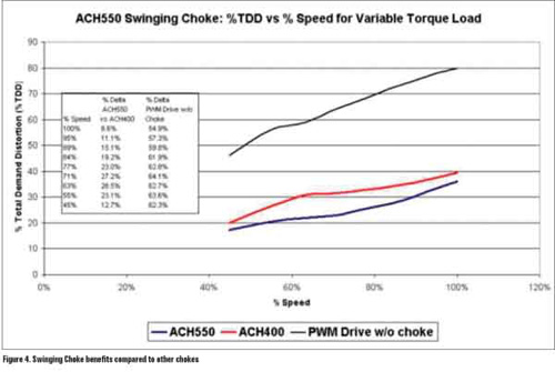
Figure 4
Limiting Harmonic Currents Reduces the Drive’s Total RMS Input Current
The swinging choke assures that the drive’s input current will never exceed the output current supplied to the motor. The rated input current marked on the drive’s nameplate is the same as the rated output current. This means that there is no need to oversize the branch-circuit wiring, disconnecting means and up-stream protection to comply with the National Electrical Code and that the drive meets the EN/IEC 61000-3-12 Standard Limits.
Limiting the harmonics generated by an individual piece of equipment frees power system capacity for adding future equipment. When each piece of new equipment includes this simple, cost-effective, built-in feature, the user reduces the risk of needing to retrofit harmonic limiting measures in the future.
(As a recommendation to specifiers, it is recommended that for the hospital environment, consulting engineers and hospital administrators should insist that all VFDs be supplied with 5% impedance line reactors, or better yet, swinging chokes.)
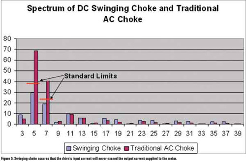
Figure 5
EMI / RFI and the EU Council Directives
Electromagnetic compatibility (EMC) is the ability of electrical/electronic equipment to operate in its installation environment while neither causing nor experiencing electromagnetic interference (EMI). EMI is any interference with normal equipment operation caused by abnormal energy entering the equipment either by conduction though wiring connections or by radiated wave reception. Radiated electromagnetic interference is also called radio frequency interference (RFI).
In the European Economic Community, the EU Council Directives set standards for various products. The EMC Product Standard for Power Drive Systems, EN 61800-3 (or IEC 61800-3) is used as the main standard for VFDs. This standard contains test procedures that are specifically suitable for drives and the standard is quite comprehensive. It covers both the drive’s electromagnetic emissions and its immunity from received emissions.
Recommendations to Specifiers
For drives with the most comprehensive electromagnetic compatibility, specifiers should require drives to meet the IEC 61800-3 Electromagnetic compatibility standards and emission limits for Restricted Distribution and installation in the First Environment. Drives that meet the above requirements will typically meet the technical requirements of FCC Part 15 including the emission limits for a Class A digital device.
Summary
This paper has discussed the energy savings possibilities when using VFDs on fan and pump applications. It has given the end user a simple method of identifying potential VFD retrofit applications. The paper has presented a brief introduction to harmonic distortion with an explanation of some reasons and methods for limiting harmonics. A swinging choke has been described as the key component of a recently developed method for limiting harmonics generated by a VFD and provided recommendations for specifiers. Finally, EMI/RFI considerations and recommendations have also been discussed for the hospital environment.


Find Us on Socials