Electrical System Grounding Requirements
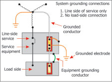
Figure 1. System grounding connections at the service or separately derived systems
Electrical power distribution systems are typically required by the designer to have one of the wires grounded or solidly connected to the earth (the neutral in a WYE system). The designer for commercial or industrial installations is typically a professional engineer who is taking the requirements of the various building systems (power, telecommunications, fire protection, security, energy management and lightning protection) into consideration for the proper grounding system. Many smaller commercial installations and virtually all residential installations do not have such sophisticated systems and the electrical contractor simply follows the minimum requirements outlined in the National Electrical Code. The electrical contractor essentially uses the Code as a design manual for lack of other guidance since these installations rarely have drawings that are prepared by professional engineers. The grounding sections of the National Electrical Code do not attempt to explain the need for grounding electrical systems and can be difficult to understand. Often, grounding systems are installed that comply with the NEC but are not at all adequate for the proper performance of the electrical system for the design life of the building.
From the 2005 NEC:
90.1(B) Adequacy.This Code contains provisions that are considered necessary for safety. Compliance therewith and proper maintenance will result in an installation that is essentially free from hazard but not necessarily efficient, convenient, or adequate for good service or future expansion of electrical use.90.1(C) Intention.This Code is not intended as a design specification or an instruction manual for untrained persons.
Grounded vs. Grounding Conductor
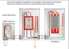
Figure 2. Grounded conductor is required to be run to each service disconnecting means enclosure
The neutral conductor in ac electrical systems not only carries the unbalanced load of the phase conductors back to the source of the current, but also limits system over voltages during transients, limits voltage-to-ground during normal system operation and facilitates the operation of overprotection devices if ground fault occurs in one of the phase conductors. The neutral point of a three-phase WYE utility transformer is connected to the earth to establish a ground reference, making that point the same potential as the earth. This conductor, commonly called “a neutral” is referred to as the “grounded” conductor in the NEC. It is connected to the earth to ensure there is no potential difference between the conductor and the earth (for personal safety) and to allow relay and control circuit operation in the event of system fault. If a neutral point is derived (as in a WYE configuration) as the utility transforms the voltage and current with several transformers, that point is solidly connected to the earth. Utilities continue to connect their system to the earth with ground rods along their transmission and distribution systems and very elaborate ground grids at substations that may carry several thousand amps during fault conditions. It is important to realize that the earth is not a destination of fault currents created by system events. The grounding features of the electrical system are used to provide a very low-impedance path for transient currents to find the neutral of the source. System-generated electrical currents have no tendency to “flow” to the earth; the earth is a poor conductor.
The situation is different for “non-system” generated currents. In this context, non-system generated currents are caused by forces outside of the generated power system, such as lightning. These currents clearly have the earth as a destination and very much want to flow into the ground. Most of the utility grounding systems are designed to allow this current to flow directly into the earth and avoid their conductors (the static wires on transmission lines are used primarily for lightning protection). Lightning produced currents do not seek the neutral point of the generated system and will do so only as a conductor to get to the earth, causing much havoc along the way.
Lightning-Protection System Requirements
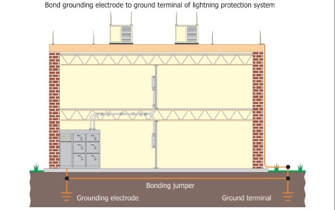
Photo 1. Typical lightning protection grounding and bonding to electrical system ground
The NEC requires the neutral of electrical systems to be grounded or to be electrically in contact with the earth. Section 250 describes the requirements for this Grounding Electrode System and describes the parts of a building that can make a minimally effective system. The grounding electrode system does more than make the connection from the neutral (or grounded conductor) to the earth. It also provides a low-impedance path for faults caused by inadvertent contact between the energized (or as the NEC describes, the ungrounded) conductor and the equipment cabinet, building structure or the other mechanical systems of a building. If properly followed, the requirements of Section 250 will provide a safe initial installation but it must be emphasized that these requirements are minimum and do not take design life into consideration.
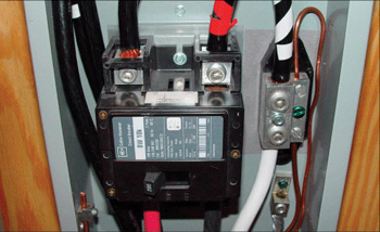
Figure 4. Main bonding jumper (screw type)
What Exactly Is a Grounding Electrode System?
The grounding electrode system for a building is comprised of grounding electrodes that are designed to make a good electrical connection with the earth to provide a low-impedance reference. [Electrodes include all types not just rod types. A rod is not an electrode until it is installed in the earth.] Remember that no current seeks the earth as a destination, only as a temporary conductor to get to the destination—the neutral point of the system. Critical components of the building need to be electrically connected to the neutral to conduct any fault currents to allow overcurrent-protection devices to operate quickly and safely. All of these parts should be solidly electrically connected (or as the Code says “bonded together”) to assure that they are at the same potential as the earth and to minimize the chance that a metallic piece of the structure could carry a line voltage and allow a potentially fatal current to flow through a person to the earth.
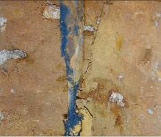
Photo 2. 5/8″ galvanized ground electrode exhumed after nine years from a test site in Clark County, Nevada
The earth connection part of the grounding electrode system was initially made by the required connection of the grounding system to the underground metallic water pipe. Municipal water systems were constructed of several miles of metallic pipe and provided an excellent ground reference. But, as more and more nonmetallic pipes were introduced into water-system supplies, municipal water pipes became unreliable as a ground reference and the Code began requiring supplemental electrodes to ensure that this connection with the earth was made. Ground rods, plates, rings and electrodes in concrete are examples of supplemental electrodes that were allowed to augment the connection to the water supply pipe, which is now viewed as a dubious grounding connection at best.
In 2005, theNECclarified connections to be used in new construction as the supplemental connections to the reinforcement bar that are used as part of the concrete structure of a building. This is commonly referred to as a concrete-encased electrode (or Ufer ground) and does provide an excellent ground reference but it may be inadequate for “non-system” generated events—like lightning—especially if any damage caused by spalling of the concrete could result in reduction in the structural integrity of the concrete. Rods, plates and rings also provide excellent earth reference and can provide protection without the concern of structural damage. There have been no documented cases of building foundations or footings being compromised by lightning events that we are aware of. An IEEE paper called, “Impulse and Alternating Current on Grounding Electrodes in Soil Environment” reports test results revealed damages by applied voltages and current levels. It should be noted that the Code recognizes the use of rod, plate and concrete-encased electrodes as ground reference and not fault-return paths, because the conductors required to connect these electrodes are allowed to be much smaller than the conductors used to connect the building steel and water or gas piping systems. Please note: metal underground gas piping is not permitted to be used as the ground electrode system, but an exposed gas piping system likely to be energized is required to be bonded to the grounding system. Simply put, the conductors used for ground reference should not carry fault currents, but the conductors going to the building steel or piping systems can carry fault currents. A conductor going to a ground rod does not have to be larger than a 6 AWG CU whereas the conductor going to building steel can easily be larger than a 3/0 AWG CU.
(A) Connections to Rod, Pipe, or Plate Electrodes. Where the grounding electrode conductor is connected to rod, pipe, or plate electrodes as permitted in 250.52(A)(5) or (A)(6), that portion of the conductor that is the sole connection to the grounding electrode shall not be required to be larger than 6 AWG copper wire or 4 AWG aluminum wire.
(B) Connections to Concrete-Encased Electrodes. Where the grounding electrode conductor is connected to a concrete-encased electrode as permitted in 250.52(A)(3), that portion of the conductor that is the sole connection to the grounding electrode shall not be required to be larger than 4 AWG copper wire.
(C) Connections to Ground Rings. Where the grounding electrode conductor is connected to a ground ring as permitted in 250.52(A)(4), that portion of the conductor that is the sole connection to the grounding electrode shall not be required to be larger than the conductor used for the ground ring.
Other Elements of the Grounding Electrode System
Rod-Type Grounding Electrodes
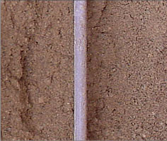
Photo 3. 5/8″ copper electroplated ground electrode exhumed after nine years from a test site in Clark County, Nevada
TheNEChas a confusing description of rod and pipe electrodes that will allow completely inadequate materials to be considered compliant with this section of the code. Section 250.52 (A)(5) states:
(5) Rod and Pipe Electrodes. Rod and pipe electrodes shall not be smaller than 2.5 m (8 ft) and shall consist of the following materials:
(a) Electrodes of pipe or conduit shall not be smaller than metric designator 21 (trade size 3/4) and, where of iron or steel, shall have the outer surface galvanized or otherwise metal-coated for corrosion protection.
(b) Electrodes of rods of iron or steel shall be at least 15.87 mm (5/8 in.) in diameter. Stainless steel rods less than 16 mm (5/8 in.) in diameter, nonferrous rods, or their equivalent shall be listed and shall not be less than 13 mm (1/2 in.) in diameter.
This section appears to allow 3/4″ EMT as a grounding electrode, but this material would disintegrate by corrosion in a very short time, assuming it could be driven into the earth. It should be understood that electrical metallic tubing is not electrical conduit or pipe as referred to in this section. The Code differentiates between conduit and tubing in Articles 342, 344, and 358 (see the definition and construction specifications for each conduit or tubing as provided in those articles). This section also puts copper electroplated ground rods into the section referred to as “nonferrous rods or their equivalent.” Copper electroplated rods are about 90% steel at the core and are not “nonferrous.”
Unlike other sections of the Code, there is no requirement for a rod type electrode to be listed for the purpose of use. There is an allowance for the use of a listed rod if the installer wants to use a rod that is smaller than 5/8″, a stainless steel rod, a nonferrous rod or the equivalent. The listing specification for these electrodes is UL 467 which clearly details the thickness of stainless steel and copper on a solid rod electrode but does not describe thickness requirements for galvanized rods which have recently gained listing to this standard. As of January 2006, the controlling NEMA specification for rods—NEMA GR1 2005—requires galvanized rods to be at least 5/8″ in diameter. So, technically, galvanized rods smaller than 5/8″ do not comply with this standard but do have a UL Listing.
This section of the NEC does not adequately specify an electrode that will provide a continuous connection to the earth for the intended life of the electrical system. Under the NEC, using a piece of 3/4″ EMT would not be considered as an acceptable grounding electrode. Using a UL Listed galvanized rod smaller than 5/8″” would be considered compliant by NEC standards, but this rod does not comply with industry accepted NEMA requirements.
A good ground reference is necessary for the proper operation of electrical devices and is essential to ensure a safe electrical system. By installing a “code-compliant” ground rod that is subject to corrosion in a fraction of the building, the contractor could inadvertently create some very serious problems well after he has finished the installation. The ground system that initially had 25 ohms or less may have no ground reference in 10 years or less with a completely compliant initial installation.
The best way to address long-term functionality of the grounding electrode – ground reference system is to look at the construction of the ground rod and consider the design elements that lead to the longest installed life to ensure a low-resistance ground reference.
Life Study of Rod Type Grounding Electrodes
Ground rods can be constructed of uncoated steel if they are equal to or greater than 5/8″ in diameter. This diameter requirement allows for mechanical rigidity for installation as well as mass to allow for deterioration by corrosive action; a ground rod that starts out at 5/8″ will take more time to corrode away than one that started out at ½”.
It is a very common misconception that the copper electroplating on a rod is used to increase the conductivity. It is not. The resistance of the earth compared to that of the rod itself makes the improved conductivity of the copper plating insignificant. Copper electroplated rods utilize the corrosion prevention characteristics of copper to extend the life of the electrode by as much as 30 years in most soils. The resistance to corrosion allows the copper electroplated rod to be smaller in diameter than the galvanized or steel equivalent. This is also true of stainless steel rods, but the cost of stainless steel is prohibitive for use in everyday installations. The corrosion resistance characteristics of copper-plated steel were demonstrated clearly in the National Bureau of Standards Circular 579 titled “Underground Corrosion.” This study examined more than 36,000 specimens testing over 300 varieties of ferrous, nonferrous and protective coating materials in 128 test sites in the United States. The study shows that a typical 10-mil copper plating on steel will provide about 40 years of service life versus 13 years for the typical 3.9-mil coating of zinc on a galvanized rod. The results of this study were further corroborated by the ongoing National Electrical Grounding Research Project test of ground rod performance, originally initiated by the Southern Nevada Chapter of IAEI. The results were definitive: The typical copper electroplated rod was virtually free of corrosion while most galvanized rods showed severe deterioration and corrosion after 11 years of service.
Grounding System Design Elements and Functional Considerations
TheCodedoes not properly address the long-term functionality of the grounding-electrode system’s connection to the earth. As ofNEC-2005, a concrete-encased electrode is required to be part of the grounding electrode system. However, it can be challenging to coordinate the installation and inspection of this electrode since it is installed during the first phase of construction of a building when there is little or no other need for an electrical inspection. Use of structural elements that may be damaged by electrical transients should also be critically examined.
Ground references provided by ground rods can provide low-resistance ground connections. But here, the Code falls short as a design manual. Even though theNECdirectly states that it is not a design manual, it is frequently used as one for most grounding electrode systems. Grounding electrodes should be selected with consideration of the design life of the installation: if the project has an intended life of 40 years, an electrode that lasts at least 40 years should be selected.
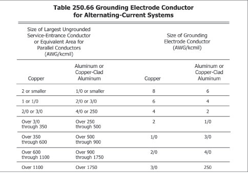
Table 1. Reproduction of NEC Table 250.66
If more than 25 ohms exist between the ground rod and the earth, methods to reduce this to desired levels should be initiated. Currently the NEC states that another ground rod be driven, whether or not that significantly improves the resistance to earth. There are several methods that can be utilized to reduce ground resistance, but after they are attempted, the ground resistance should be checked again to see if the remediation efforts were successful.
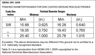
Table 2. NEMA GR1 2005
UL 467 and NEC Article 250 should be clarified to remove some of the obvious shortfalls and ambiguities. Until these efforts are made, it is incumbent on the electrical contractor to avoid simply installing to the minimum requirements of the NEC and to install a ground system that will provide service for the life of the installation.
NEMA is a registered trademark of the National Electrical Manufacturers Association. NEC is a registered trademark of NFPA, and the National Electric Code is a copyright of the National Fire Protection Association. UL is a registered trademark of Underwriters Laboratories, Inc.