Grounded Systems Generally Required

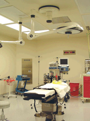
Photo 1. Health Care Facility Room
The definition title wet locations in 517.2, under “Patient Care Area,” has been revised for the NEC-2008 to wet procedure location. This revision provides more specific criteria of the wet locations covered by the definition in 517.2 and provides a bit more differentiation from the wet location definition in Article 100. See IAEI’s book, Analysis of Changes NEC-2008 for additional information about this revision.
Isolated Power System Branch-Circuit Conductors
Isolated power systems and their proper installation and use involve specific criteria. Insulation and identification of the branch-circuit conductors is more specific than that allowed in the general rules of the Code. The dielectric insulation resistance values are critical for system functionality. Minimizing the length of branch-circuit conductors and using conductor insulations with a dielectric constant less than 3.5 and insulation resistance constant greater than 6100 megohm-meters (20,000 megohm-ft) at 16°C (60°F) reduces leakage from line to

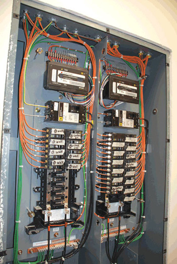
Photo 8. Brown and orange XHHW conductors installed for isolated power-system branch circuits
ground, reducing the hazard current. THHN/THWN typically do not offer these high dielectric insulation resistance values. XHHW is one type of conductor insulation that meets the dielectric insulation values required by these systems (see photo 7). The manufacturer’s instructions and installation guidelines for these systems will often specify the type of conductor insulation required or acceptable for use with the particular system. Sometimes a maximum length for the circuits is also specified. Wire-pulling compounds that have a deterioration effect on the dielectric values of conductor insulation are not permitted to be used when installing these branch-circuit conductors [see 517.160(A)(6)].
Branch-Circuit Color Code Required
The Code does not include a color code for general wiring branch-circuit conductors. However, there is a specific color code required for the branch-circuit conductors supplied by the isolated power system. Section 517.160(A)(5) requires the branch-circuit phase conductors to be orange (for conductor No. 1) and brown (for conductor No. 2) (see photos 8 and 9). Yellow is the required color for the third conductor if a three-phase isolated power system is used.

Photo 9. Brown and orange XHHW conductors installed for isolated power-system branch circuits
NEC-2008 Update: As of this writing, Section 517.160(A)(5) has been revised to require that the orange, brown, and yellow conductors used with isolated power systems are now required to be identified with a distinctive colored stripe other than white, green, or gray. See IAEI’s book, Analysis of Changes NEC-2008 for additional information about this revision.
Where the isolated power system branch circuits supply 125-volt 15- or 20-ampere receptacles, the orange conductor is required to be connected to the terminal on the receptacle intended for the grounded conductor (see photo 10). Since there is no grounded conductor supplied by these systems, this clarification was made inNEC-1999.
Grounding and the Reference Grounding Terminal

Photo 10. Orange ungrounded circuit conductor is required to be connected to the receptacle terminal that is normally intended for a grounded conductor.
Although the isolated power system itself is ungrounded, equipment grounding conductors are required to be installed to the receptacles and connected to the grounding terminal of such receptacles to serve as a ground reference for connected equipment or appliances. The equipment grounding conductors associated with the isolated power system branch circuits are permitted to be installed either inside the conduit or raceway or on the outside of the raceway. This is in contrast to the requirements of 300.3(B) and 250.134, which generally require the equipment grounding conductor to be run in the same raceway, cable, or trench. This minimizes the effects of impedance in the equipment grounding circuit in ground-fault conditions for normally grounded systems. The need is different for ungrounded (isolated) systems because the systems are monitoring leakage current and will not facilitate an overcurrent device in the event of a single phase-to-ground fault from any of the ungrounded conductors of the system. It is recommended to install the equipment grounding conductor in the raceway with the circuit conductors. This offers greater protection in the event of a second phase-to-ground fault condition on the system [see 517.19(F)]. The equipment grounding conductors with the branch circuits of isolated power systems are required to be connected to the reference grounding bus in the listed isolated power system equipment. This reference grounding bus is connected to the equipment grounding conductor supplied with the primary circuit feeding the isolated power system (see photo 8). If there are any electrostatic shields present with the system, they are required to be connected to the reference grounding bus within the equipment. This is also required by NFPA 99.

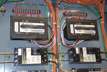
Photo 11. Line isolation monitor of an isolated power system (digital)
Where isolated power systems are used to supply power circuits to task illumination, selected receptacles, and fixed equipment in critical care areas that utilize anesthetizing gases, or the system is used in special environments, the isolated power system is required to be supplied by a circuit that supplies no other load. This circuit is required to be connected to the critical branch of the emergency system, which is part of the essential electrical system [see 517.30(C)(2)]. Circuits supplying primary side of isolated power system transformers must not operate at more than 600 volts between phase conductors and are required to be protected with properly rated overcurrent devices. The equipment grounding conductor with the primary circuit for the isolated power system is required to be not less than the sizes given in Table 250.122, based on the rating of the primary overcurrent device supplying the isolated power system.
Line Isolation Monitor

Photo 12. Line isolation monitor of an isolated power system (analog)
The use of an isolated power system requires, as part of the system, a line isolation monitor (LIM) that is installed so as to be visible to personnel in the care areas where the isolated power circuits are used. The line isolation monitor includes a green (status OK) lamp and a red (hazard leakage current) lamp, both of which are to be visible by personnel (see photos 11 and 12). The monitor is supplied as part of the isolated power system panel, but many times remote monitors are installed where the equipment is located outside the critical care area. An audible warning signal is initiated when the total hazard current (consisting of possible resistive and capacitive leakage currents) from either isolated conductor to ground reaches a threshold value of 5 mA under nominal line voltage conditions. The line monitor is not required to alarm for a fault hazard of less than 3.7 mA or for a total hazard current of less than 5 mA [see 517.160(B)(1)]. It is often a desirable design specification to locate the ammeter and LIM so that they are conspicuously visible to persons in the anesthetizing location.
System Testing
Isolated power systems are tested for acceptance upon initial installation for insulation resistance values and potential differences to the reference grounding bus in the equipment. Although the NEC does not require initial performance testing of these systems, this testing is a requirement of NFPA 99 and must be performed periodically thereafter. If the system is modified or altered after initial installation, it must be tested again. The manufacturers of isolated power systems often provide this service when the systems are first installed. Many testing organizations can also provide these testing services. Many of the major health care facilities perform these tests on a regular schedule with their own trained qualified personnel. Appropriate records are required to be kept of such tests. See NFPA 99 for specifics on these types of tests and required testing time frames.
Summary
Isolated power systems were primarily utilized as a protection technique to minimize the possibilities of explosions and fires in flammable anesthetizing locations in health care facilities. Areas in health care facilities that utilize flammable anesthetics are classified as hazardous locations and require isolated power systems as well as other hazardous (classified) location wiring and protective techniques. Isolated power systems are still utilized, but more as an optional protection technique or as required in wet procedure locations as defined in Article 517 because interruption of power by ground-fault circuit interrupters cannot be tolerated. The isolated power system provides an equal and effective means of electrical safety for the patient and personnel in health care facilities. These special systems are operated ungrounded, but must be monitored. Not only is it important to install these systems correctly and test them upon initial installation for acceptability, but it is equally important that the personnel utilizing such systems be trained and qualified in their proper use. This includes both the electrical staff and the medical personnel providing the patient care in these critical care areas. The authority having jurisdiction should work closely with installers when such systems are being installed in the health care facilities. Installation instructions and recommended testing criteria provided in the installation instructions and the applicable codes and standards are of critical importance for installers as well as inspectors. Chapter 5, Special Occupancies, many times modifies the rules in chapters 1 through 4 to be more restrictive. The installation of isolated power systems is one such case and is worth a closer look. This article is not totally inclusive of all situations and uses of isolated power systems, but does cover many of the requirements.
Find Us on Socials