Transfer equipment installations can be extremely complex, even for optional standby arrangements that are critical to business operation. This is the final installment in a series of articles examining transfer equipment used in optional standby systems for commercial applications. In Part I of this series, we covered the fundamentals of transfer equipment used in optional standby systems and the use of key interlocks to provide a safe, simple, and reliable means of transfer. Part II explored transfer equipment options along with guidance, questions to ask, and considerations for each system. This article will focus on transfer equipment for 3-phase, grounded systems. It will discuss requirements for the selection of three- or four-pole transfer and the impact to code-compliant installations. It will also discuss larger, more complex transfer applications found in data centers and hospitals.
Three- or Four-Pole Transfer?
NEC permits the standby generator to be connected as a separately or non-separately derived system and this should be the first question asked when reviewing a system design plan. Aseparately derived systemis defined in Article 100 as “A premises wiring system whose power is derived from a source of electrical energy or equipment other than a service. Such systems have no direct electrical connection, including a solidly connected grounded circuit conductor, to supply conductors originating in another system.” Section 702.10 specifies that portable generators can also be connected as a separately or non-separately derived system. Understanding if the system was designed as separately or non-separately derived connection is essential for transfer applications. Planning for one type of system and getting the other can lead to serious system performance issues.
Four-Pole Transfer System Considerations – Ground Fault
Separately derived systems require four-pole transfer equipment in order to provide the normal and alternate sources with mutually exclusive grounded circuit conductors (neutral), see figure 1. This is an important requirement since for separately derived systems the generator is required to be grounded perNEC250.30. The use of four-pole transfer equipment and resulting separation of the systems allow the overcurrent protective device to recognize load unbalance current and avoid nuisance ground-fault tripping. Figure 2 illustrates that this is accomplished by preventing the neutral current from having a parallel path through the equipment grounding conductor (EGC). Another benefit of using four-pole transfer equipment in a separately derived system is demonstrated in figure 3. When a real ground fault occurs the current is not allowed to return to the source using the grounded conductor (neutral). This allows the overcurrent protective device to accurately recognize the fault and protect the system. Failure to use four-pole transfer equipment for a separately derived system would adversely affect the equipment ground-fault protection and ability to recognize load unbalance. A more complicated and costly modified differential ground-fault system would have to be designed and installed.

Figure 1. Four-pole transfer equipment used for separately derived system connection

Figure 2. Load imbalance current path with four-pole transfer equipment. Note that having the service neutral disconnected from the load prevents neutral current from returning through the main bonding jumper (MBJ) and equipment ground to the alternate source.

Figure 3. Example of possible ground-fault current flow with four-pole transfer equipment. A ground fault on the load of the transfer equipment cannot return to the alternate source using the grounded circuit conductor (neutral) but instead must return through the equipment grounding conductor or bus.
Four-Pole Transfer System Considerations — System Stability and Safety
NEC 250.30(A)(1) requires separately derived systems to have a system bonding jumper similar to the main bonding jumper required for services. A concern and potential issue arises if the system bonding jumper is not installed or has been removed. When the load is transferred to the alternate source the electrical system no longer has a ground reference, see figure 4. This situation can lead to system stability issues with abnormal phase-to-ground voltages which potentially damage electronic devices and controls. Stability can also be affected if the system has significant unbalanced line-to-neutral loads causing imbalanced line-to-neutral voltages. Since the alternate source is not grounded and four-pole transfer equipment was used, detection and locating system ground faults become complicated. Failure to locate and repair single phase-to-ground faults can result is serious power system damage if the fault escalates to a multiple phase-to-ground fault.

Figure 4. Four-pole transfer equipment where the alternate source generator does not have a system bonding jumper
Four-pole transfer equipment solutions often have an option to include an overlap or break before making contact for the (neutral) grounded circuit conductor. Line-to-neutral voltage disturbances caused by switching the grounded circuit conductor can cause problems with sensitive electronic components and should be considered in the system design. For this very reason, there are industries and engineers that will not consider switching the neutral due to the risk of loss to expensive electronics that are running or communicating with vital operations.
Four-Pole Transfer System Considerations – Code Compliance
It may be challenging to determine if code requirements have been met for a separately derived system when the alternate source is not on-site. This is often the case when a portable generator is intended to be the alternate source. Will the portable generator have the system bonding jumper installed? The lack of a proper system bonding jumper can result in an unsafe system condition by allowing the system to lose its reference to ground (ungrounded system) and by preventing the installed equipment ground-fault protection from performing as designed.
Three-Pole Transfer System Considerations
The most common transfer system solutions are three-pole. Non-separately derived systems will require three-pole transfer equipment because the alternate source generator is connected as a feeder. This connection uses the normal source main bonding jumper which connects the grounded conductor (neutral) to grounding electrode conductor as the grounding means for the alternate source grounded conductor. NEC-2005 250.24(A)(5) specifies that “A grounding connection shall not be made to any grounded conductor on the load side of the service disconnecting means except as otherwise permitted in this article.” However, NEC-2008 indicates the following: “A grounded conductor shall not be connected to normally non-current-carrying metal parts of equipment, to equipment grounding conductor(s), or be reconnected to ground on the load side of the service disconnecting means except as otherwise permitted in this article.” Since this is a non-separately derived system, load side grounding is only permitted for separate building or structure applications where an equipment grounding conductor is not run with the building supply. An example of a non-separately derived system using three-pole transfer equipment is shown in figure 5. Since the normal and alternate sources share a direct connection to the grounded circuit conductor, installations where equipment ground-fault protection is required for the alternate source will require a modified differential ground-fault system to properly discern load imbalances and system ground faults. This is a benefit for installations intending to use a portable generator. Unlike the four-pole separately derived situation, three-pole transfer equipment solutions for this case will already provide a modified differential ground-fault system and thus provide equipment ground-fault protection regardless of the portable generator system bonding jumper condition. It is still important to understand the generator bonding because if three-pole transfer is used and the generator is bonded there will be a parallel path for neutral current flow along the equipment grounding conductors between the service and generator.

Figure 5. Three-pole transfer equipment used in non-separately derived system
Potential ungrounded system stability and safety concerns which can arise in four-pole transfer systems do not occur in three-pole transfer systems. There is a continuous, direct connection to the grounded circuit conductor and service main bonding jumper.
Advanced Applications
There are power transfer applications more complex than the traditional two source transfer discussed up to this point. In particular, the systems seen in data centers and hospitals are not only more complex but also much larger than most transfer systems. The following sections will provide basic insight into the systems typically supplied in hospitals and data centers and how optional standby systems are utilized.

Data Centers
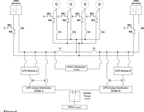
Figure 6. Typical example of the power distribution one-line diagram in a data center
Advanced Applications – Hospitals
Article 517 details the requirements of power transfer in health care facilities including the division of loads into essential and nonessential systems. A typical hospital power flow diagram is shown in figure 7. The loads classified as emergency are segregated from normal distribution equipment and fed from unique automatic transfer switches. However, there are loads classified as nonessential which must meet Article 702 optional standby system requirements. These loads can be supplied from the same utility and generator sources as the emergency loads as long as they originate from separate vertical switchboard sections and the wiring is kept entirely separate from the emergency system wiring. Section 700.5 requires the generator to be rated for all possible loads or have some type of load management with priority given to emergency loads.

Figure 7. Typical power system transfer structure for hospitals. Neutral connections to ATSs were removed for clarity.
A Final Note on Ground-Fault Protection
Optional standby systems continue to grow in size to not only power a few business critical functions but are being sized to maintain continuity of business for an entire facility.NEC702 does not exempt a system from ground-fault protection in accordance withNEC215.10. The risk of losing your electrical system for an extended period due to not protecting the system with ground fault far outweighs the possible short-term condition of taking the system down and saving the distribution system due to a fault. Even ground-fault protection on an emergency system is permitted. The only disconnect that exists with regard to ground-fault protection is inNEC517.17 where it is prohibited between the generator and the essential electrical system and on the load side of the transfer switch of the essential electrical system. Remember that ground-fault protection protects your electrical system to ensure it will continue to operate after appropriate maintenance. Removal of ground fault simply provides a few moments of operation while the switchboard and/or system is potentially destroyed by the fault taking place.
Plan Review and Inspection
Transfer equipment applications can range from simplistic installations to very complex optional standby systems for data centers and hospitals. The considerations for three- or four-pole transfer, ground-fault protection of equipment, system stability and safety, as well as code-compliance challenges must be integrated to work as a system. Clearly these considerations have dependencies and therefore must be considered as part of an overall system design to ensure that the optional standby system provides the desired benefits and does not negatively impact normal system performance. In particular, understanding the design intent as separately or non-separately derived and attention to four-pole transfer systems using portable generators is required to provide a safe, code-compliant installation. So here are a few items you can review:
1. The first question is always – Is this anNEC700, 701 or 702 system?
2. Is the system configured as separately or non-separately derived?
3. Does the transfer switch (3- or 4-pole) match the configuration of the system’s source?
4. Is the system grounding system appropriately installed and bonded?
5. Is this system large enough for ground-fault protection and is it installed?
6. Do we have the appropriate disconnects and overcurrent protection located and sized appropriately?
7. Is the alternate source a portable generator? If so, how is the system configuration and necessary generator bonding condition communicated?