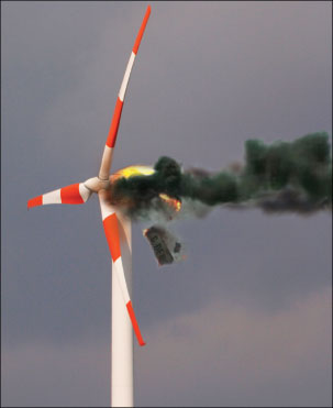
Power continuity is essential in wind power projects where a tripped overcurrent device due to ground fault can have serious economic or operational consequences. An arcing phase-to-ground fault can totally destroy the equipment. Consequential downtime adds to the economic loss. Four typical grounding methods for generators and power systems are examined for these factors and the article concludes that resistance grounding provides the best protection against arcing ground-fault damage in wind power projects with distribution systems and improves reliability and availability of the power systems.
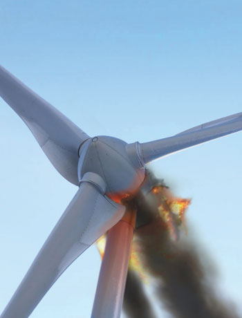
Photo 1. Wind Turbine Fire
Grounding of Generators
The generators can be ungrounded, high-resistance grounded, low-resistance grounded or solidly grounded. In solidly grounded generators, very high fault currents can flow in the event of a phase-to-ground fault with a possibility of extensive fault damage[4]and consequential loss of revenue. In addition, there is a possibility of high harmonic current flows when the generator and step-up transformers are solidly grounded. Applying low-resistance grounding reduces the potential damage due to phase-to-ground faults, but the generator must be tripped and isolated with a consequential loss of revenue. With high-resistance grounding, a phase-to-ground fault can be annunciated[4]and the generator kept running. An ungrounded generator can be used if the cable length to the step-up transformer is relatively small. With long cable lengths in multiple generator systems, the generator to transformer section becomes susceptible to transient overvoltages in case of intermittent phase-to-ground faults. This could lead to subsequent 2ndphase-to-ground failure elsewhere in the network leading to catastrophic damage.
Power Collection System
The transformer secondary is usually connected in delta and can be 5, 15, or 36 kV for areas which follow ANSI specifications, and 3.3, 11, 20, or 33 kV for areas following IEC specifications.
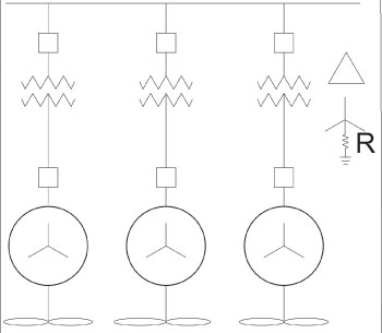
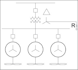
This arrangement can be a single generator to transformer, as shown in figure 1 or multiple generators to a transformer, as shown in figure 2. Power is collected through many such transformers on a wind farm in the medium voltage (MV) distribution network, and exported to the utility network at the point of common coupling, as shown in figure 3.[2]
MV Circuits
Solidly grounded circuits lead to high-fault currents due to phase-to-ground faults and may cause extensive damage and high-step or touch voltages. Low-resistance grounding thus lowers the phase-to-ground fault current and allows time-current coordinated trips to isolate the faulty circuit. High-resistance grounding is not suggested, since the cable capacitance can be quite high due to the total length of the MV cable at the collection voltage. When the MV network is left ungrounded on the occurrence of a phase-to-ground fault, the voltage on the other two phases to ground rises to phase-to-phase value, but the operation of the wind farm remains uninterrupted.[3]
An ungrounded MV network is subjected to transient overvoltages on the two healthy phases in the case of intermittent or arcing type phase-to-ground faults, due to the capacitive charge build-up in the cables.
MV Electrical Distribution Networks
Wind farm collection networks are simple radial circuits with switching devices for isolation and switching.[1]Balanced 3-phase networks are suitable for connecting large wind generators. The secondary of the generator step-up transformer can be Y- or Delta-connected. In Y-connected transformers the neutral point is directly accessible and hence can be easily grounded. In Delta-connected transformers an accessible neutral point is created by using a grounding transformer as shown in figure 4. The usual practice is to ground the neutral point at one location only.
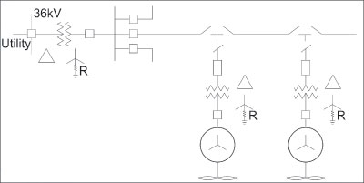
Figure 3. MV Collection Network
Electrical Protection
With high-resistance grounding of the generator step-up transformer, fast acting ground-fault relays can be applied in the generator circuit. Low-resistance grounding by neutral grounding resistors or artificial neutrals is suggested for the MV network. The fault currents in the MV collection networks can be small due to high source impedance and long lengths of cables. In some cases, fuses cannot be relied upon to quickly clear the fault; hence, ground-fault relays and circuit breakers are required. It is important to isolate the faulted section quickly. Correct discrimination is obtained by the application of ground-fault relays.
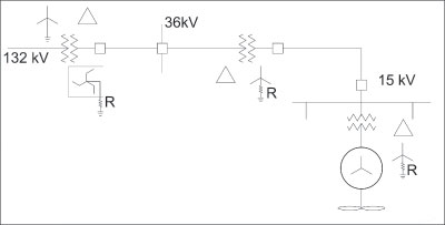
Figure 4. MV collection network with artificial neutral
Additional Electrical Protection
Conclusion
Ungrounded delta systems have many operating disadvantages, including high transient overvoltages and difficulty in locating faults. Solidly grounded neutral systems limit the system potential to ground, and speed the detection and location of ground faults. However, the system must be shut down after the first ground fault and there is a potential for extensive arcing fault damage. Applying coordinated ground-fault protection is very difficult and almost impossible with multiple generators.
Low-resistance grounded neutral systems limit the magnitude of the ground-fault current so that serious damage does not occur. The system must still be shut down after the first ground fault. This level of resistance grounding is generally used on medium- and high-voltage systems, above 6.9 kV.
If the power system is changed to high-resistance grounding then the ground-fault current can be reduced to 10 A or less, which has significant impact on reducing the equipment damage. In addition, it ensures that the wind power system continues to operate and does not suffer trip-out of a faulted generator.