
As the Nation slowly works its way out of the COVID-19 pandemic and various supply chain issues associated with that pandemic are resolved, photovoltaic (PV) electrical power systems are continuing to proliferate throughout the country. Lowering prices on PV systems, even when dealing with inflation, are resulting in larger PV systems being installed on dwellings throughout the country. Also, greater awareness of the various environmental disasters, such as hurricanes and forest fires that are disrupting utility electrical services, are driving the market of PV systems. PV systems connected to the load side of the service disconnect are attractive because of their ease of installation; however, National Electrical Code (NEC) requirements on the size of the PV system that can be connected in that manner pose system size limitations.
The PV system connected to the supply side of the main breaker will allow larger PV systems to be installed, which will be addressed in this article.
THE BASICS
Load-side connections are limited as follows. For example, a 100-amp service can accept the output of a 3840 W (16 A @240 V) utility-interactive PV inverter. A 200-amp service can accept the output of a 7680 W (32 A @240 V) utility-interactive inverter after code considerations are applied.
The solution to these limits is to connect the PV system output to the supply side of the service disconnect, and, in many cases, the allowable current from the PV System ac output increases to the rating of service, commonly 100 A or 200 A.
Let’s examine some of the supply-side connections that have been used in the past as well as currently but which may no longer be allowed or were improper according to NEC requirements and Underwriters Laboratories (UL) Safety Standards.
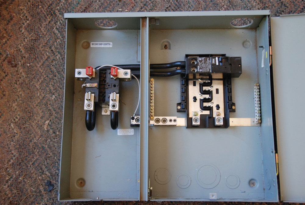
Many dwellings have a meter-main combination service entrance load center where the meter socket and the load center are in a single enclosure. See photo 1. The meter socket terminals are connected directly by short lengths of conductors or busbars to the main breaker in the load center section of the combination device. While these conductors appear to be readily accessible and easily tapped for a PV supply-side connection between the meter and the main breaker, this is not a legal connection that can be made in the field. The meter-main combination device is a listed device and may not be modified in the field. There are special circumstances where it may be possible to have a certified UL 508 shop make a connection and recertify or list the device, or it may be possible to have an Underwriters Laboratory or other nationally recognized testing laboratory (NRTL) make a field inspection. Neither of these solutions is inexpensive and would probably cost far more than replacing the combination device with a separate meter socket and separate load center and making the connection between the meter socket and load center with a junction box between the two devices.
Another solution that has been common in the past but is significantly restricted on new construction under the 2020 NEC is the use of one of six breakers in an installed load center which has six breaker positions, all acting as main breakers with no single main breaker for the entire device. If on an existing installation, one of the six breakers is unused, it may be used as a supply-side connection because it is essentially the main breaker, and the PV is being installed using that breaker as the output overcurrent protective device for the utility interactive inverter. The size/rating of the PV system output may be as high as the service rating (or the rating of the load center, whichever is smaller) if a breaker of that size can be installed in one of the six positions. That connection is made directly to the load center bus bar, which is connected to the meter. Section 230.71 in the 2020 NEC significantly restricts the use of more than one service disconnecting means per set of service entrance conductors. There are exceptions, but they may not be widely applicable to dwelling units. The six main breaker panel boards will become increasingly rare.
A new Section 705.11, Supply-Side Source Connections, has been added to the 2020 NEC to further define and clarify the requirements of such connections.
LOOKING DEEPER
Supply-Side Connections. Section 230.82(6) allows PV systems to be connected on the supply side of the service disconnect if provided with a disconnecting means listed as suitable for use as service equipment and has overcurrent protection as specified in Part VII of Article 230. See 705.11.
Section 705.11(A) restricts the sum of the power source continuous current output ratings on the service to a value not to exceed the ampacity of the service conductors. The output of a Power Control System meeting the requirements of 705.13 shall be considered when making these connections. The Power Control System may have an output breaker larger than would normally be allowed, but the control mechanism would limit the total power source current to the busbar connected to the service conductors to the maximum rating of those service conductors.
It is not clear, to the author, at this time, of the status of the single and two-family emergency disconnect required by Section 230.85 in the 2020 NEC. This could be a service disconnect located outside the building and followed by an inside-the-building service disconnect/overcurrent protection in a load center. The meter location is not specified. The question that comes up; where should a supply-side PV system connection be made in this situation? Possibly the 2023 NEC will clarify this situation.
Conductor Sizing. Conductor sizing from the point of connection on the service entrance conductors to the first overcurrent protective device on the output of the utility-interactive inverter is controlled by the requirements listed in 705.11(B). They shall be sized according to the requirements found in 705.28 but in no case sized smaller than 6 AWG copper or 4 AWG aluminum.
Generally, the current used in the conductor sizing calculation is the rated continuous output current of the PV inverter 705.28(A). That current (called the maximum circuit current) is then used in one of three calculations to determine the largest current [705.28(B)]. The largest resulting current is used to size the conductors.
- The maximum circuit current shall be multiplied by 125% without the application of any conditions of use factors.
- The maximum circuit current after the application of conditions of use factors.
- Section 240.21(B) is used where the output circuit is connected to a feeder and is the conductor size is smaller than that feeder.
Neutral conductors in single-phase, line-to-neutral circuits shall have the same size as the size of the required circuit conductors. Where used only as voltage or phase detection, they shall be permitted to be sized per 250.102. See 705.28(C).
Conductor Installation. The installation of these conductors must be installed using the requirements in Section 230.30 (Underground Service Conductors) or Section 230.43 (Wiring Methods for 1000 V, Nominal or Less). It should be noted that both sections deal with the installation of service conductors or service-entrance conductors. Section 230.43 lists a wide variety of cables and methods that can be used for these conductors.
Overcurrent Protection. Overcurrent protection varies with the exact routing and type of building that is involved with these conductors between the utility-interactive inverter output and the connection to the service conductors. Section 705.11(C) establishes the various requirements which should be reviewed in some detail. Section 705.30 requires that these power source output circuit conductors be provided with overcurrent protection, and if multiple power sources are connected to the same circuit, that circuit shall have overcurrent protection from all sources.
The rating of the overcurrent device in sources other than generators shall be rated to carry not less than 125% of the maximum currents as calculated in 705.28(A).
Where the power source output circuit conductors make their connection to the service entrance outside of a building, they shall be provided with overcurrent protection devices in a readily accessible location outside the building or at the first readily accessible location where the power source conductors enter the building.
The disconnecting means for this circuit where fuses are used as the overcurrent protective device shall be located on the service side of the fuses.
These conductors shall be protected with one of the following methods:
- For dwellings, the overcurrent device shall be located within 3 m (10 feet) of the conductor length from the point of connection to the service. In other than dwellings the overcurrent protection device shall be located within 5 m (16.5 feet) of conductor length from the connection to the service.
- In other than dwellings, the overcurrent protective device may be located within 20 m (71 feet) of conductor length from the point of connection to the service where cable limiters are installed in all ungrounded conductors within 5 m (16.5 feet) of conductor length from the point of connection to the service.
Equipment Used for Connections. Section 705.11(D) specifies that the connectors used to make these connections must be listed for the application as described in 110.14 and comply with all instructions provided with the connectors. An alternative is to make modifications to existing equipment with the manufacturer’s instructions and then have the modification evaluated for the application and have a field inspection label applied.
Although not specifically addressed by the Code, AHJs may see some of the following connections in various PV installations. One option might be to obtain double-conductor lugs for the meter socket output conductors (if supplied by the socket manufacturer) and make the PV connection at that location.
In a similar manner, double-conductor lugs may be available from the load center or main breaker manufacturer that would facilitate a supply-side connection on the input terminals to the main breaker.
Another option might be to use an enclosure holding the PV inverter output overcurrent device and appropriate terminals to make the connection in that enclosure. A supply side connection in the service entrance cable between the meter and the main breaker will require some sort of enclosure to hold the splice at this point. That enclosure could perform double duty as the splice location and the location of the overcurrent protective device for the PV system output. Conductor fill limitations should be addressed.
Any equipment, including the meter socket enclosures under the exclusive control of the electric utility, must have those connections and modifications approved by the electric utility.
Ground Fault Protection. Section 705.11(E) establishes that ground fault protection is required where the connections are rated at 1000 amps or more in solidly grounded wye services exceeding 150 volts to ground but not exceeding 1000 V phase-to-phase. Ground fault protection meeting requirements of 230.95 shall be provided. This ground fault protection provides protection from the circuits and equipment leading to the PV system.
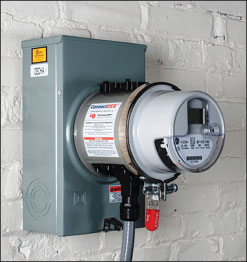
Other possibilities. In some jurisdictions, the local utilities will allow the use of a meter socket adapter. See photo 2. This meter socket adapter fits between the existing meter and the existing meter socket and provides a connection point for a supply-side connection to the service conductors. These are made by a number of manufacturers and are listed, and some even have an internal measurement system that provides an external reading of the output power and energy to the utility from the utility-interactive inverter connected to the supply side connection. Keep in mind that the utilities in most jurisdictions control access to the meter socket and will have to approve any adapter that is used on a PV system installation.
SUMMARY
Larger PV systems are being installed in increasing numbers due to price reductions and the growing trend to use more renewable energy throughout the country. These larger systems, by necessity, require a supply-side (of the service disconnect) connection to the service conductors. The 2020 National Electrical Code provides requirements for these conductors and connections in Section 705.11 and related sections.