 The combination inspector is an integral part of the inspection process in many inspection agencies across the country, including the entity for which I have worked for close to two decades. I was hired as an electrical inspector; however, on my first day (within the first hour) one of the supervisors placed a stack of code books in front of me, including the UBC, UMC, UPC[1]and the only one I recognized — theNEC. The supervisor who placed the books in front of me then announced I was one of their new “combination inspectors.” Thus began a crash course of training in subjects to which I had never before been exposed. I thought I had it dialed in: I was a master electrician, knew the NEC pretty well and had finally got a job where I could utilize the knowledge I had, but that changed the first day.
Over the years, I’ve observed that for most combination inspectors, the weakest field of knowledge is electrical. Most lack sufficient knowledge of the NEC and have limited field experience. Since electrical is my specialty, I requested to start an electrical training program to help my fellow employees to better understand and enforce the electrical code. Through the last fifteen years, I have provided help to over sixty inspectors, not only to perform electrical inspections, but to pass their electrical inspector certification exams. These individuals have come from all areas of the construction industry, and each started at different levels of electrical knowledge and some were having difficulty passing the electrical inspection certification exam.
There can be several different classifications of combination inspections. Some areas have only residential combination inspectors; others have full combinations inspectors who do all types of commercial and industrial inspections. As we approach the electrical code for combination inspections, we will attempt to go into details which will benefit all these diverse levels of inspections. We will approach the National Electrical Code from chapters 1-4, as these are the basic articles that apply to most general installations. We will then proceed in sequential order, while trying not to jump around the Code any more that we have to. Many have stated that the electrical code is the hardest of all the trades to learn, so the goal is to make learning this Code as simple and straightforward as possible.
One of the major stumbling blocks to learning the electrical code is that it has an entire specialized language which regular users understand and take for granted. However, to those who haven’t been exposed to the field, we might as well be speaking a foreign language. Such things as ohms, watts, conduit bodies, cord caps, connector bodies, fault current and so on are not part of the normal daily conversation for non-electrical trades.
My dad was a professional math and science teacher, and I often asked him how he was able to get his point across and make sure his students understood his lessons. He explained that you have to observe the students and be able to recognize that look that comes over them when all of a sudden you’ve crossed the line into neverland. It’s at that point you stop and approach the subject from a different angle. This different angle often includes hands-on visualization of the subject or item which you are discussing.
So, I adopted this point of view, and tried to provide hands-on illustrations. I keep boxes of materials, including breakers, GFCIs, keyless fixtures, and several other examples of electrical apparatus which allows a hands-on approach to learning. It is very helpful to the students to take these items and touch, inspect and even disassemble them, in order to see how and why they function. Through photos and descriptions, I plan to share several of these examples during upcoming articles.
Understanding Basic Principles
So where do we start? First, we have to understand some of the basic principles of electricity, what it is and how we use it. Electricity is an unseen force which we have learned to control and utilize to benefit us in many ways. However, when it gets out of control we have a situation which can have many disastrous results. These situations have resulted in many of the code requirements we have today.
The three most basic terms we use are voltage (measured in volts), resistance (measured in ohms) and current (measured in amps). Current is commonly referred to as amperage or ampacity.
To understand the distinct properties and relationship of these terms, we will use a plumbing analogy. The voltage is like the water pressure in a plumbing system, the current is equivalent to the rate of flow of water, and the resistance can be equated to the pipe size (see figure 1). We can have 120 volts which would be like 50 PSI (pounds per square inch), and a system with 480 volts would be like 200 PSI. In a 50 PSI system, we can control it fairly easily, and water would only shoot a short distance if a pipe rupture occurs. However, when we have a system at 200 PSI, it will take a lot more effort to control it and it can shoot for quite some distance. This is similar to how voltage works, the higher the voltage the better the equipment must be for us to control it.
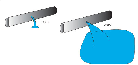
Figure 1. Voltage is like water pressure in a plumbing system.
Resistance would be equated to the size of the pipe in a plumbing system. Similar to pipe sizing, smaller electrical wires have higher resistance, so they let smaller amounts of current through than do larger wires at the same voltage.
Now let’s talk about current (see figure 2). If the pressure were equal for two different pipe sizes, the smaller pipe will only allow so much water through for a given time. For instance, if a 1/2˝ pipe will allow 1 gallon of water in a minute, a 2˝ pipe at the same pressure for the same minute could produce several gallons of water. So if we have 5 amps of current and we short it out we get a small arc such as you would see when you connect your car battery. But if you have a 100-amp circuit and you short it out, you’d think you had just done some pretty serious arc welding with a very large arc welder. Keep in mind welders wear special gear to perform their job, just like electricians who work on gear with higher levels of voltage must wear special gear. So amperage or current equals the volume of flow.
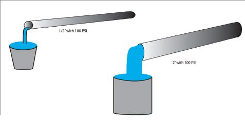
Figure 2. Current equals the volume of flow.
Ohm’s Law
This may seem to over simplify the concepts to some, but this is a basic way of understanding the concepts of electricity. There are many other important concepts, but for our basic approach this analogy works. Now we have to approach the infamous Ohm’s Law. Ohm’s Law is the relationship of four different measurements of electricity. Figure 3 is the Ohm’s Law wheel.
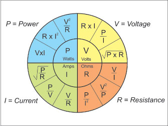
Figure 3. Ohm’s Law wheel
As you can see from the wheel in figure 3, we have talked about a third of the wheel already: volts, ohms and amps. Now let’s talk about watts.
Watts are basically a measurement of consumption. Your meter on your house is often referred to as a watt-hour meter, and it measures the amount of watts you consume (and then you are billed accordingly!). We should be familiar with watts from lamps we have used for years, a 100-watt light being the most common electrical item you have probably purchased for years. Now with the more efficient methods of lighting we have, you will see compact fluorescent lamps which will state 100 watts of light for 27 watts of power.
Now let me simplify the Ohm’s Law wheel to show you the three most common wedges of the wheel we use for basically 90% of the calculations we will do.
The most common wedge used is the middle wedge of the amps quadrant to find the amperage when we know the watts and the voltage: I (amps) = P (watts) / V (volts). So if we have a 100-watt light on a 120-volts system, how many amps will this lamp pull? 100 watts / 120 volts = 0.83 amps. This is one formula that you just simply must memorize. The second formula we will use is to find the watts when we know the amperage and the voltage. This will utilize the bottom formula of the quadrant for P (power, which is measured in watts). So P (watts) = V (volts) x I (amps), or 120 volts x .83 amps = 100 watts.
The last part of the wheel we will deal with at this time is how to find the voltage when we know the amperage (I) and the wattage (P). So we will use the middle wedge of the volts quadrant, V (voltage) = P (watts) / I (amps). So 100 watts / 0.83 amps = 120 volts.
For now these are all we have to deal with, but as we get further into the code and start to talk about resistive and inductive loads we will revisit portions of the Ohm’s Law wheel. For a basic understanding, we are fine with just these three.
This will conclude the first article in this series, so please spend some time practicing the three formulas we’ve reviewed above and see what the amperage and wattage are of various items around your house. Check the labels on your equipment and see if you can find the amperage if they give you the watts and vice versa if they give you the amps find the wattage.
In order to understand the NEC, one must be familiar with the format or layout of the Code, which is explained at NEC 90.3. In the next article, we will start with a few items in Article 90 and then dive into the definitions which are important to know before proceeding into the body of the code.
References
[1]UMC, Uniform Mechanical Code
UPC, Uniform Plumbing Code
UBC, Uniform Building Code


Find Us on Socials