Conductor sizes and overcurrent device ratings are critical to the safe, long-term operation of any electrical system, but are of particular importance in PV systems where the outdoor environment can be extreme and the PV modules will be sourcing current for 40 years or more. Historically, most residential and light commercial electrical wiring and inspections of these systems have involved indoor wiring at room temperatures [30°C (86°F) or less]. The ampacity tables in the NEC Section 310.15 and Table 310.16 were developed with those conditions in mind. The commonly used molded-case circuit breaker has a terminal temperature limit of 75°C and is rated for use with conductors with 75°C insulation. They have a rated maximum operating temperature of 40°C.
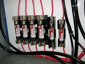
Photo 1
With these conditions and equipment characteristics in mind, the typical electrician doing indoor wiring has generally used the 75°C insulated conductor ampacity tables in Table 310.16 and not bothered too much with temperature corrections (310.15) and terminal temperature limits [110.14(C)] since they were not necessary or were included in the tables being used.
However, direct current (dc) PV conductors normally operate in an environment that is too hot for conductors with 75°C insulation. Conductors with 90°C insulation must be used and appropriate temperature and conduit fill corrections must be applied along with verifying that connected equipment terminal temperatures (60° or 75°C) are not exceeded. To do otherwise and use the short-cuts of the old days will result in conductors that may be not suited for the application and that may be larger than code requirements resulting in unnecessary costs.

Photo 2. Fused PV combiner with large and small cables
Throughout the Code, circuits are sized based on 125% of the continuous load plus the noncontinuous load. See 210.19(A)(1) and 215.2(A)(1). This requirement establishes a situation where conductors and overcurrent devices are not subjected to continuous loads (currents) more than 80% of rating. (Note: 1/1.25 = 0.80 and we can either divide or multiply depending on how the calculations are being accomplished).
Electricians and PV installers typically use the 125% factor and then apply the conditions of use factors (temperature and conduit fill)sequentially. The NEC,in a careful reading of the two referencedsections, does not require that both factors be applied at the same time. See the 125% requirement below.
In the Code, we have at least two or three requirements that must be met in sizing conductors.
First is the definition ofampacityfound in Article 100. Ampacity is “The current in amperes that a conductor can carry continuously under the conditions of use without exceeding its temperature ratings.”
Next is the 125% requirement in 210.19(A)(1) and 215.2(A)(1): “The minimum feeder circuit conductor size,before the application of any adjustment or correction factor,shall have an allowable ampacity not less than the noncontinuous loads plus 125 percent of the continuous loads” (emphasis added). This requirement ensures that conductors and overcurrent devices are not operated continuously at over 80% of rating.

Photo 3. Fuse AC and DC ratings will be different.
Then, Section 110.14(C) requires that the temperature of the conductor in actual operation not exceed the temperature rating of terminals on the connected equipment.
An added requirement for any listed equipment such as overcurrent devices is that they not be used in a manner that deviates from the listing or labeling on the product [110.3(B)]. Most PV source-circuit combiners operating outdoors in the sunlight will have internal temperatures that exceed the 40°C rated operating temperatures of commonly used fuses and circuit breakers.
The following method of determining ampacity meets the three code requirements above and finds the smallest conductor that can be used to meet these requirements. It also determines the rating of the overcurrent device where required.
Step 1. Determine the continuous current in the circuit.
PV dc circuits and PV ac circuits are not “load” circuits so we will use the termcurrentinstead ofload. For code calculations, all dc and ac PV currents are considered continuous and are based on worst-case outputs or are based on safety factors applied to rated outputs.
A. PV DC Circuits.In the dc PV source and dc PV output circuits, the continuous currents are defined as 1.25 times the rated short-circuit current Isc(marked on the back of the module). If a module had an Iscof 7.5 amps, the continuous current would be 1.25 x 7.5 = 9.4 amps [690.8(A)(1)].
If three strings of modules (module Isc= 8.1 amps) were connected in parallel through a fused source circuit combiner, the PV output circuit of the combiner would have an Iscof 3 x 8.1 = 24.3 amps. The continuous current is this circuit would be 1.25 x 24.3 = 30.4 amps [690.8(A)(2)].
B. AC Inverter Output Circuits.In the ac output circuits of a utility-interactive inverter or the ac output circuit of a stand-alone inverter,

Photo 4. Copper busbars are used instead of cables.
the continuous current is taken at the full power rated output of the inverter. Itis notmeasured at the actual operating current (which may be a small fraction of the rated current due to a small PV array connected to a large inverter) of the inverter. Usually the rated current is at the nominal output voltage (120, 208, 240, 277, or 480 volts). The rated output current is usually specified in the manual, but may be calculated by dividing the rated power by the nominal voltage. For stand-alone inverters, which can provide some degree of surge current, it is the rated power that can be delivered continuously for three hours or more [690.8(A)(3)].
In some cases, the inverter specifications will give a rated current that is higher than the rated power divided by the nominal voltage. In that situation, the higher current should be used.
For a utility-interactive inverter operating at a nominal voltage of 240 volts and a rated power of 2500 watts, the continuous current would be:
2500 W/240 V=10.4 A.
A stand-alone inverter with a model number of 3500XPLUS operates at 120 volts and can surge to 3500 watts for 60 minutes. However, it can only deliver 3000 watts continuously for three hours or more. The rated ac output current would be:
3000 W/120 V = 25 A.
C. Battery Currents.The currents between a battery and an inverter in either a stand-alone system or a battery-backed up utility-interactive

Photo 5. Improperly specified and sized cable
system must be based on the rated output power of the inverter (continuous for three hours or more) at the lowest input battery voltage that can provide that output power [690.8(A)(4)]. Normally the output current from the battery in the inverting mode is greater than the current to the battery in the charging mode. This current is usually marked on the inverter or found in the specifications.
The battery discharge current can be calculated by taking the rated output power, dividing it by the lowest battery voltage that can sustain that power, and also by dividing by the inverter dc-to-ac conversion efficiency at that battery voltage and power level. For example:
A 4000-watt inverter can operate at that power with a 44-volt battery input voltage and has a dc-to-ac conversion efficiency (inverting mode) of 85 percent. The dc continuous current will be:
4000 W/44 V/0.85 = 107 A.
On single-phase inverters, the dc input current is rarely smooth and may have 120 Hz ripple current that is larger in root mean square (RMS) value than the calculated continuous current. The inverter technical specifications should list the greatest continuous current.
Step 2. Calculate the rating of the overcurrent device, where required.
Since PV modules are current limited, overcurrent devices are frequently not needed for one or two strings of PV modules connected in parallel. In systems with three or more strings of modules connected in parallel, overcurrent devices are usually required in each string to protect not only the conductors, but also the module internal connections.
A. Rating Determined from Continuous Currents.The overcurrent device rating is determined by taking the continuous current for any of the circuits listed in Step 1 and increasing the continuous current by 125% (or by multiplying by 1.25). Non-standard overcurrent device values should be rounded up to the next standard rating in most cases.
In a very few rare cases, an overcurrent deviceinstalled in an enclosureor an assembly may be tested, certified and listedas an assemblyfor operation at 100% of rating. In these cases, the overcurrent device rating is the same as the continuous current and no 125% factor is used. The author knows of no overcurrent devices installed in an enclosure for PV systems that have such a rating.
B. Operating Temperature Affects Rating.Overcurrent devices are listed for a maximum operating temperature of 40°C (104°F). PV combiner boxes operating in outdoor environments may experience ambient temperatures as high as 50°C. Exposed to sunlight, the internal temperatures may reach or exceed 55–60°C. Any time, the operating temperature of the overcurrent device exceeds 40°C, it may be subject to nuisance trips at current values lower than its rating. In this situation, the manufacturer must be consulted to determine an appropriate derating. At high operating temperatures an overcurrent device with a higher rating will activate at the desired current. In PV source circuits, the new rating of the revised overcurrent device (under cold weather conditions) must not exceed the ampacity of the conductors or the maximum series fuse value marked on the back of the module.
Step 3. Select a conductor size.
The conductor selected for any circuit must meet both the ampacity requirement and the 125% requirement. The correctly sized cable is the larger of A or B below.
A. Ampacity Requirement.The conductor, after corrections for conditions of use must have an ampacity equal to or greater than the continuous current found in Step 1. See Article 100, Definition of ampacity.
B. 125% Requirement.The cable must have an ampacity of 125% of the continuous current established in Step 1. See 215.2(A)(1).
Example 1.Three (3) conductors are in a conduit in a boiler room where the temperature is 40°C. The continuous current in all four conductors is 50 amps. A copper, 90°Cinsulated cable is specified.

Photo 6. PV containers may operate above 40°C.
Temperature correction factor = 0.91, Conduit fill correction factor = 1.0
Step A, Ampacity Rule: Required ampacity at 30°C is 50/0.91/1.0 = 54.9 amps and this would require an 8 AWG cable.
Step B, 125% Rule: 1.25 x 50 = 62.5 amps and this would indicate a 6 AWG cable.
The 6 AWG cable is the larger of the two and is required.
Example 2.Now there are six (6) conductors in the conduit and the temperature has increased to 50°C. The continuous current is still 50 amps.
Temperature correction factor = 0.82, Conduit fill factor = 0.8
Step A, Ampacity Rule: 50/0.8/0.82 = 76.2 amps and a 4 AWG cable is needed
Step B, 125% Rule: 1.25 x 50 = 62.5 amps calling for a 6 AWG cable.
The 4 AWG cable is the larger of the two and must be used.
Step 4. Terminal temperature limits
A. The terminal temperature limits marked on the equipment must be used. If no temperatures are marked, then a 60°C limit is used for circuits rated at 100 amps or less or cables 14–1 AWG. For circuits rated greater than 100 amps and for conductors greater than 1 AWG, a 75°C terminal temperature limit will be used. See 110.14(C).
The following method is a terminaltemperature estimationmethod and is not an ampacity calculation method. It is used after the conductor size has been selected based on the ampacity calculation.
Take the conductor size in Step 3 above. Find the lowest terminal temperature limit for this conductor at any termination. Use that terminal temperature limit (either 60°C or 75°C) to enter the ampacity Table 310.16. For the conductor size selected, read out the current in the correct column, either the 60°C column or the 75°C column. There are no temperature adjustments or conduit fill adjustments to this current.
The current from the table must be equal to or greater than 125% of the continuous current. And, if the conductor meets this requirement, then the terminal temperatures are going to be less than the 60°C or 75°C limit for that conductor and that continuous current. The 125% factor is a fudge that accounts for many items not calculated in this simplified temperatureestimationprocess.
Example 3.Take the 8 AWG conductor and 50 amps of continuous current used in Example 1 above. This conductor is connected to a terminal with a 60°C marking.
From Table 310.16, an 8 AWG conductor in the 60°C column can carry a current of 40 amps.
We take 125% of the continuous currents of 50 amps.
1.25 x 50 = 62.5 amps.
This is larger than the 40 amps from the table, and this terminal will be heated above 60°C.
If we increase the conductor size to 6 AWG, the table gives us 55 amps, still less than 62.5 and too hot.
Increasing the conductor size to 4 AWG will give 70 amps from the table; and since this is greater than the 62.5 amps, we will be assured that the terminal will stay below its 60°Ctemperature limit.
Example 4.Use the 4 AWG conductor selected in Example 2 connected to a terminal with a 75°Ctemperature limit. The continuous current is 50 amps. Taking 125% of that continuous current yields:
1.25 x 50 = 62.5 A.
A 4 AWG conductor in the 75°C column of Table 310.16 shows a current of 85 amps. Since this is greater than the 62.5 amps, the conductor will operate cooler than the 75°C terminal temperature limit. No increase in conductor size is necessary.
Step 5. Verify that the overcurrent device protects the conductor selected under the conditions of use.
Where an overcurrent device is required, it must protect the conductor under operating conditions (conditions of use). Conductors may be protected using the round up allowance found in 240.2(B).
Example 5.A circuit has a continuous current of 70 amps. After conditions of use (4 conductors in the conduit, 48°C) are applied, a 3 AWG, 90°C conductor is selected to meet all ampacity and 75°C terminal temperature requirements.
The ampacity after conditions of use have been applied is:
110 x 0.8 x 0.82 =72.2 A.
The required minimum overcurrent device for this level of continuous current is
70 x 1.25 = 87.5 A.
A 90-amp overcurrent device would typically be used. A few people have suggested using an 80-amp overcurrent device, but that would result in running it at more than 80% of rating and in dc PV circuits could result in nuisance trips during short periods of cloud enhanced irradiance.
However, the largest overcurrent device that could be used to protect the 3 AWG conductor with an ampacity of 72.2 amps is an 80-amp overcurrent device and a 90-amp overcurrent device is the smallest allowed in this circuit.
The conductor size would have to be increased to 2 AWG for full compliance with NEC requirements.
The ampacity of a 2 AWG, 90°C conductor under the conditions of use is:
130 x 0.8 x 0.82 = 107 A.
The required 90-amp overcurrent device can protect the 2 AWG conductor.
Summary
PV installers, plan reviewers, and inspectors need to know how to do conductor sizing and overcurrent device ratings properly to get safe, reliable, and cost effective PV systems. This procedure for sizing conductors and overcurrent devices meets NEC requirements. In general, it can be used for any type of electrical circuit except possibly HVAC and other motor protection circuits. A part of this procedure is in Section 690.8(B) of the 2011NEC.
For Additional Information
If this article has raised questions, do not hesitate to contact the author by phone or e-mail. E-mail: jwiles@nmsu.edu Phone: 575-646-6105
See the web site below for a schedule of presentations on PV and the Code.
A color copy of the latest version (1.91) of the 150-page, Photovoltaic Power Systems and the 2005 National Electrical Code: Suggested Practices, written by the author, may be downloaded from this web site: http://www.nmsu.edu/~tdi/Photovoltaics/Codes-Stds/Codes-Stds.html
The Southwest Technology Development Institute web site maintains a PV Systems Inspector/Installer Checklist and all copies of the previous “Perspectives on PV” articles for easy downloading. Copies of “Code Corner” written by the author and published in Home Power Magazine over the last 15 years are also available on this web site: http://www.nmsu.edu/~tdi/Photovoltaics/Codes-Stds/Codes-Stds.html