Welcome back as we continue to discuss the 2011 National Electrical Code for the combination inspector. We are finally getting into the body of the code with Article 110, which covers the basic requirements for electrical installations and applies throughout the code, unless specifically overruled in any article in chapters 5 through 8. Some of the items covered in this article are the requirements for examination, installation and use, terminations, and access to and spaces about electrical equipment. Over the years I’ve often had inspectors and electricians ask me where in the code it states some basic rule, and more often than not it is a requirement in Article 110.
The first requirement is in 110.2, which is a very simple statement that conductors and equipment shall be acceptable only if approved. We’ve already covered what approved means in a previous article, but for review it means identified, listed, labeled, or approved by the AHJ.
Eight Conditions
Next we learn the eight conditions considered for examination, identification, installation and use of equipment. Some of the more important considerations are: mechanical strength, electrical insulation, heating effects and arcing effects. For the complete list please refer to 110.3(A). Even the full list includes only some of the conditions that may need to be considered for equipment. The code can’t possibly cover all the requirements for all types of equipment, which is why equipment is made to a certain set of requirements known as astandard. These standards are created through a consensus process by various industry participants, and are a continuous work in progress as technology and manufacturing practices are always improving and changing. The last thing to consider in this area is that just because something is listed and labeled doesn’t mean that when it is installed it will be right. It is quite possible to install equipment in a manner not recommended or anticipated by the manufacturer. As a result, the code requires equipment to be installed in accordance with its listing and labeling and with any instructions included in the listing or labeling.
Voltages and Conductors
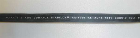
Photo 1. Common wire labeling information
We also have general rules for voltages, conductors and sizes of conductors. In summary, the voltage shall be the voltage at which the system operates and equipment must be rated not less than the voltage of the circuit it is used in. When the word “conductors” is used in the code, it is understood that it refers to copper conductors unless otherwise specified. This is done for simplicity when applying code, and it doesn’t infer that one type of conductor is superior to another or is preferred by the code. Wire is sized in either American Wire Gauge (AWG) or circular mils for the larger sizes. When we use circular mils, the size is generally listed as a number of “kcmil,” meaning a thousand circular mils. For instance 250 kcmil means 250,000 circular mils. Outside of the code, you might still see references to “mcm” or “MCM” which is an old designation that means the same thing as “kcmil.” (See photo 1 for wire legend.)
Now comes one of the most basic rules. I still get a chuckle when I read 110.7, which is titled “Wiring Integrity,” which requires that we make installations without having any shorts or ground faults. My first thought is,Well, that’s obvious, but I guess we still have to have it in writing.
Fault Current
The next item of discussion I generally have with my classes is regarding fault currents. Available fault current is the amount of current that is able to be delivered to a system at a certain point. Fault current can be affected by several factors, including the distance from the source, size of the source, and the various components in the system. Fault currents generally run into the thousands of amps. It is not unusual to have over 50,000 amps of current available in larger systems and between 4,000 and 8,000 amps in residential systems, depending on how close you are to your transformer. So how do we control that large amount of fault current? Overcurrent devices have a rating known as ampere interrupting capacity (AIC), which indicates the amount of current a device can safely interrupt without causing catastrophic damage to itself. Breakers generally range from 5 kAIC to 65 kAIC, and of course the price increases as the interrupting capacity increases. Fuses also have these ratings, but the most common fuses used today have 200 to 300 kAIC. So from this discussion, we learn that we have to be aware of the fault currents in a system and whether or not our equipment can handle that fault current. In the 2011 edition of theNEC, we have some new requirements in 110.24 regarding the labeling of an installation with the available fault current and some requirements when modifications are made to the installation.
Series Rating
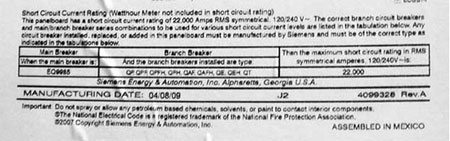
Photo 2. Series label
In some cases, we use a process known as “series rating” to handle the fault current while avoiding having to use overcurrent devices that are fully rated for the fault current. In a series rated system, the manufacturer has tested certain equipment components with other components and found that the upstream devices will limit the pass-through fault current to an acceptable level to prevent damage to the downstream device. The tricky part of this is that you have to make sure you only use items specifically tested as a series combination, and you cannot deviate from the exact system as tested by the manufacturer. This method is often frowned upon due to its potential compliance issues and the inability to alter the installed system. I’ve never been a fan of it myself, as it leads to field issues during work performed later or service work by those who do not recognize that they are dealing with a series system. “Series combination systems” are at times used for existing locations to prevent costly equipment changeouts; however, this has to be done under the supervision of an engineer. In either case, these systems must now be marked in a readily visible location. The labeling shall state that the system is a “Series Combination System Rated _____ Amps. Identified Replacement Components Required.” (See photo 2 for an example of series rating in a residential service panel.)
Installation Rules
We continue now with some installation rules, the first of which states that we cannot expose items to environments for which they are not listed to be used. This could include water, gases, fumes or other environmental factors which would or could cause damage. The most obvious example is equipment intended for dry locations that is exposed to a wet environment.
Section 110.12 requires that installations shall be installed in a neat and workmanlike manner. This raises the question: what is a neat and workmanlike manner? This is one of those items that can be subjective and at times totally unenforceable, since what looks good to one individual may not look good to another. However, we can get some guidance from NECA Standard 1,Standard for Good Workmanship in Electrical Construction.
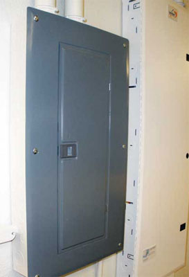
Photo 3. Securely mounted
This section goes on to require that when we have unused openings in equipment, we have to secure these and make sure they are properly closed to maintain the original integrity of the equipment. We also have to keep the equipment from being damaged or contaminated. This applies throughout the entire project, since contamination by plaster or paint can cause overheating and arcing. Often when we have a contamination issue due to construction activities, the next step is someone attempting to clean it. This often exacerbates the problem instead of solving it. I once found painters soaking large frame breakers in paint remover to get paint off of them; needless to say, we had to have brand new gear to fix that situation. (Also see photo 2 for warning about contamination warning.)
We are required to securely mount equipment. I have seen one prohibition in this rule on a high percentage of tests that people have taken for certification, and that is that we are not allowed to use wood plugs in masonry, concrete, plaster or similar materials. The reasoning is that wood plugs simply don’t hold up and are likely to pull out, so we don’t have a securely mounted system when we use wood plugs. (See photo 3 for a securely mounted example.) The next requirement deals with cooling and ventilation of equipment. Some equipment depends on natural circulation and convection for cooling. If equipment is designed to be installed in a certain manner to allow cooling, we have to recognize this and insure we get the installation done in the recommended manner.
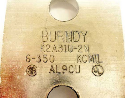
Photo 4. Typical markings on a wiring lug
Termination requirements are a part of the code that I emphasize strongly, as I believe that many of the failures we have in electrical installations are directly related to improper terminations. Having done a lot on mechanical work through the years, I understand the critical nature of connections for many items. Whether it is an engine in a car or a receptacle in a house, if it is not connected properly it will fail. It’s just a matter of time until this occurs, and the time to failure is proportional to how poorly the connection is done. One consideration for terminations is the connection of dissimilar metals. Some materials will work with others and some will not, specifically copper and aluminum shall not be intermixed in a terminal where such intermixing causes a reaction. If a termination device is rated for both copper and aluminum, then it can be done. Most of our larger conductor termination lugs are now made of aluminum and are plated so they can be used with copper. (See photo 4 for information on a termination lug.) On smaller devices, it depends on how they are tested, so the rule here is that we have to verify the listing and labeling to see exactly what each termination is listed for. Sometimes this will require the installation instructions from the carton to verify.
Now that we have the materials issue considered, we have to verify that we make the connection to the approved tightness. This is done by verifying the torque value for that device and utilizing the proper tool to ensure we make that connection to that torque value. So is a standard screw driver or a folding Allen wrench set sufficient to make sure we get the right torque value? I venture to say no. I know from testing performed recently that approximately 75 percent of the terminations made without using the proper tool were not within the specification recommended by the manufacturer. (For more information on this study, go to http://www.iaei.org/magazine/?p=5017 and read the article “The Difference Between Success and Failure – How a Torque Wrench Improves System Reliability,” published July 2010.) Over 30 percent of the connections were less than half the recommended torque. (See photos 5 and 6 to see a torque screwdriver and a factory label showing torque values for terminations)
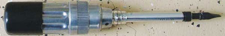
Photo 5. Torque screwdriver
So we’ve learned we have to pay attention to connections of wire to equipment, and this includes both large and small connections. To do this properly, we have to check the equipment to verify the type of conductor, the size of conductor, and method of connection (set screw, crimp, solder lugs, wire binding screw, or studs and nuts that have upturned lugs). Each type of device has a unique manner of installation which must be performed properly. For a typical aluminum lug, the device will usually be marked as AL7CU or AL9CU. Receptacles will be labeled CU, CO/ALR or AL/CU. The AL means that that device is ok to use with aluminum; CU means it is ok with copper.
Temperature Ratings
Did you notice the 7 and the 9 in the label of the lugs in the last paragraph? This leads into another factor to consider when making terminations, the temperature rating of the termination. The 7 stands for 75°C, and the 9 stands for 90°C. In 110.14(C) we cover the temperature requirements. This temperature rating matches the ampacity or size of the conductor to the rating of the connection. Again, we have some general rules, and the first is that for equipment rated 100 amps or less or marked for 14 through 1 AWG wire, conductors shall be used at the 60°C ampacities in Table 310.15(B)(16). I know we haven’t gotten to chapter 3 yet, but Table 310.15(B)(16) lists the loads that are permitted for various wire types at various operating temperatures. The second general rule states that for equipment over 100 amps, terminations shall be used with wire rated 75°C.
Now you know things just can’t be as simple as that, and of course there are more exceptions and requirements. First, you can always use wire rated at a higher temperature as long as you do not load it more than the rating of the lug. For instance, you may use 90°C wire for a termination on a 60°C lug as long as you protect that wire with an overcurrent device that will limit the load on the wire to the 60° range for that size wire. Now for the second allowance, you may use wire at the 75°C range below 100 amps if the wire and the lugs are rated for 75°C. This naturally leads to the next question, well can I use wire at the 90°C rating if I have 90°C lugs? Well, not so fast. That would make sense, but there’s always a little hitch, and here is the hitch on this: even though we have lugs rated 90°C, the equipment which houses the devices with the lugs is rated only for 75°C. Therefore, we are limited to the 75°C ampacities on those conductors.
The issue isn’t quite as simple as it appears on the surface. Part of the design and testing of equipment and terminations is evaluating the dissipation of the heat that builds up at a termination point and in the equipment. So in order to get rid of the heat, the manufacturers rely on the conductor to provide a heat sink to conduct heat away from the device in many cases. Standards for many types of electrical equipment, such as panelboards, limit their use to 75°C, so manufacturers can’t list the equipment for 90°C. Heat is a critical factor for electrical equipment and, generally speaking, we try to control the temperature of our equipment and make sure it isn’t subject to overheating as this will lead to premature failure or nuisance failure.
To sum up the temperature portion of this area of the code, it is the principle of the weakest link in a chain. If you have any portion of a circuit that is rated at 60°C, then you are not allowed to load that circuit above the 60° ampacity rating of that conductor. So a 60°C conductor with 75°C lugs is limited to 60°C; or 75°C wire terminated on a receptacle listed at 60°C is again limited to 60°C. If everything is listed at 75°C, you can load that wire to the 75°C ampacity. If we install 90°C wire on 75°C lugs, again we would be limited to 75°C ampacity. So the obvious question at this point is, why do we have 90°C wire? We will get to that in a later article, and there is an advantage to using wire with a higher temperature rating.
We’ve covered a good portion of Article 110 to this point. In the next article we will continue with Article 110, covering working clearances and space around electrical equipment and requirements for electrical rooms. Until then, remember to review the code as you review these articles. I’m covering what I consider to be the highlights of the code and some of the ways to apply it, but there is no way to hit every little detail in an article so you’ll need to at least read through each of the provisions on your own. See you in the next issue.