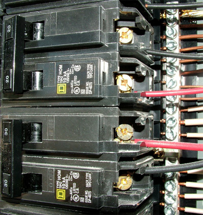
Photo 1. A multi-wire circuit connected to a common trip breaker which will provide simultaneous disconnection
Specific-Purpose Branch Ciruits
Article 210.2 references Table 210.2 which provides a list of specific-purpose branch circuits found within other articles of theCode. Please make a note of this table and review it so you will be aware that if you are dealing with any of the types of equipment listed in the table, you will know exactly where in theCodeto find those requirements.
Section 210.3 goes into the rating of branch circuits, laying out some general rules which basically state that the branch-circuit rating shall be that of the overcurrent device protecting it. So for other than individual branches, standard rating will be 15, 20, 30, 40, and 50 amps. One last requirement states that if using larger conductors having a higher ampacity, the rating of the branch circuit must still be equal to the specified overcurrent device.
To elaborate a little on this, suppose we have a very long run and are worried about voltage drop, so we decide to increase the size wire normally used for, say, a 20-amp circuit (which would be 12 AWG copper); it would still be a 20-amp branch circuit because that is the rating of the overcurrent device. A common example of this application is street or parking lot lighting, where we have very long runs between poles and the length of the entire circuit would be extremely long. It is common to run 4 AWG conductors which have an ampacity rating of 85 amps at 75°C for these lighting circuits and then to protect them with a 20-amp breaker. This increased wire size will minimize voltage drop, which we need to address so we don’t damage the utilization equipment connected. So in spite of the size wire, if it is protected by a 20-amp overcurrent device, it is a 20-amp branch circuit.
Multi-wire Branch Circuits
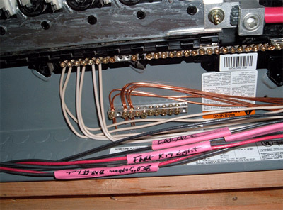
Photo 2. This is a common method of grouping done in the residential construction. However, please note the new requirement may also have to include the neutral in the grouping.
With 210.4 we go into detail regardingmulti-wire branch circuits. We previously discussed these when we were in Article 100, but a quick review is in order here. A multi-wire branch circuit is a circuit with more than one ungrounded or hot conductor sharing a common neutral or grounded conductor. In a single-phase system, we would have two hot conductors for one neutral and in a three-phase system we could have three hot conductors to one neutral. In 210.4 we find the conditions that apply to these circuits. The first requirement deals with the fact that all the conductors of a multi-wire branch circuit must originate from the same panelboard, I’ll go into this after we cover the other few items, some of which are fairly new to theNEC. In addition to originating from the same panel, a means to disconnect all the ungrounded conductors simultaneously must be provided. This is done through the use of multi-pole disconnecting means which has each pole of the ungrounded conductors interlocked so they open together (see photo 1). Multi-wire branch circuits are limited to only line-to-neutral type loads, although there are two exceptions you should review in yourNEC.
The next requirement, which is relatively new to theCode, is the requirement for grouping these conductors. “Grouping” means providing some means (such as wire ties or a similar method) to easily identify which conductors within a panel are part of each multi-wire branch circuit. One method seen in the residential construction area has been the practice of taking a piece of the outer sheath of a nonmetallic-sheathed cable and slipping it over the conductors of the multi-wire circuit, and they may also write on the sheath what that circuit feeds, for example “kitchen receptacles” (see photo 2).
Let’s spend a moment regarding one of these items and discuss it in detail, the requirement for all of the conductors of a multi-wire branch circuit to originate from the same panelboard. Years ago, I was working on a renovation job in an old warehouse for one of our electrical supply houses. On one wall, they had four subpanels side by side, with a common gutter above and below. Part of our job was to replace each of these with new panels. We were planned to replace them one at a time to minimize customer inconvenience and to keep the facility open. As we proceeded with this project, we would shut off all the breakers in one panel, shut off the feeders and start to disconnect each wire. As we started to remove the neutrals, all a sudden we would have more locations that would lose power.
>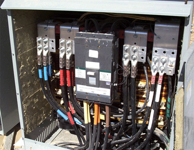
Photo 3. Step-down transformer which is providing the second voltage in the same premise thus triggering the requirement for proper identification of branch circuits
Why was this happening? The answer was quite simple: throughout the fifty years that this facility had been in business, they had numerous “helpers” who would connect circuits to a breaker in one panel and the neutral would come from another panel. We also found several multi-wire branch circuits which would have one breaker in one panel and the other breaker in another panel, and who knew where the neutral connection was made (sometimes in a gutter and even one time just under a screw driven into the back of one of these gutters). Lucky for us, the owners of the property understood the conditions we were working with, and also understood that we would discover issues which could not be planned for and we would just have to make the best of it. If 210.4 had been followed throughout the history of this facility, we wouldn’t have had these issues.
The new requirements in this article will make it easier for the inspector and the service electrician to identify a multi-wire branch circuit, and to insure it is wired to the correct simultaneous disconnecting means and terminated on the proper phases within the panel. Just remember, the multi-wire branch circuit’s ungrounded conductors must terminate on different phases. I know I’ve mentioned this in previous articles, but a little review is always good.
Identification of Branch Circuits
In Article 210.5 we cover the identification of branch circuits. The first item is the identification of thegrounded conductor, which is actually covered in Article 200 and discussed in the previous article. Next is mentioned the identification of theequipment grounding conductor, which is clearly covered in Article 250, and will be discussed further in a future article. The item primarily covered in 210.5 is the identification of theungrounded conductors(or hot) conductors. There are several misconceptions dealing with identifying these conductors, some based on history along with a variety of local interpretations across the country.
What theCodeactually states is that first you have to have one condition for 210.5(C) to apply, and that is this, the premises must have more than one nominal voltage system. Does that mean 120/240 as two different voltages? No, it applies in situations such as where we have a 277/480 system providing power for equipment and lighting, then have a step-down transformer which provides 120/208 voltage system to supply the outlets for typical office equipment (see photo 3). Once we have met this condition, we have to identify the conductors for each system by phase or line and system (i.e., 120/208 or 277/480) at all termination, connection and splice points.
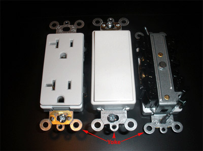
Photo 4. Branch-circuit devices mounted on “yokes.”
So how is this commonly handled in the field? It is very common for contractors to select certain color conductors for each voltage system. The most frequently chosen arrangement seen for a 277/480 system is brown, orange and yellow for the phase conductors and a grey neutral, and for the 120/208 conductors it is common to use black, red and blue with a white neutral. Notice I said most commonly chosen, there is nothing in this part of theCodewhich states a certain color scheme is required for the phase conductors.
One other key item to this identification requirement is that the method utilized for identification shall be permanently posted at each branch-circuit panelboard or similar branch-circuit distribution equipment. What we usually see is a plaque or similar signage at each panelboard or distribution board that informs everyone working on that system what color is what voltage and which phase.
You will notice that above I said what is “commonly” or “frequently” done. In some cases, the engineer of record will specify which color is to be used for each voltage and phase. Unfortunately, the contractor sometimes neglects to read these details, which may cause an issue. Some jurisdictions have color codes which they enforce on a local basis, and if you are working in an area new to you, it would be wise to check local codes. Often I’ve been asked if it isn’tCodeto use the color scheme as outlined in the paragraph above. At one time, decades ago, theCodedid have a requirement for specific colors, however that was removed. Is it good workmanship to use consistent color identification in this manner? Yes, but it isn’t required byCodein every case, only where we have two voltage systems on the same premises.
Let’s explore a few possibilities which may be used. First, you can order colored wire to match your chosen scheme for each phase. This would include feeders and branch circuits, and this has become more common in the last decade with manufacturers producing colored conductors for all sizes and methods of wiring, including many cable assemblies. However, this is not the only way.
Another option would be to use a common color such as black and to re-identify it at each termination, connection and splice point. This is not the most labor friendly method, but I have seen it done in cases where the proper colors of wiring were not purchased or were not available. Let me share a little issue with re-identification which I’ve seen in the past. A contractor had purchased thousands of feet of MC cable for a large job and all of it was black, white and a green ground. No problem, as long as it was used on only the 120/208 system and he phase-taped each black to identify which phase to which it was connected. However, when he attempted to use the same cable on the 277/ 480 volt system for the 277-volt lighting, he created another problem. Thinking he could re-identify the blacks to whichever color he needed, he proceeded to do so; however, he neglected to review Article 200 which talks about re-identification of neutrals and doesn’t allow phase taping on conductors for 6 AWG and smaller. So how was he going to comply with the color scheme he had on the signage he had posted at each panelboard? We asked him and, as often happens, he realized what they’d done and corrected the problem once reminded of theCoderequirements. This is one of the miracles of working in the inspection profession: often the Code violations disappear overnight.
Branch-Circuit Voltage Limitations
In 210.6, the requirement provides us with voltage limitations based on different applications. The first is the limit applied to occupancy: in dwelling units and guest suites of hotels, motels and similar locations, the voltage shall not exceed 120 volts between conductors for luminaires (lights) and cord- and plug-connected loads 1440 volt-amperes nominal or less than ¼ hp equipment. This is equal to 12 amps for 120-volt cord- and plug-connected loads or about 6 amps related to the hp rating. So the common question I get at this point is, “What about the wall A/C-heaters in hotel rooms?” If it is above the ratings just discussed, they are allowed to utilize a higher voltage; and the wall units usually have a resistive heat strip within them, definitely putting them well above the 1440 volt-amperes.
Sections 210.6(B), (C), (D) and (E) give the limitation requirements for voltages of different types of lighting and utilization equipment. These have really never been much of an issue related to inspections since manufacturers address these requirements in the design of their products. Just be aware of “creative” wiring methods which could create misapplications of equipment outside the intended use. When you see something that just doesn’t look right, you may not know exactly how to apply theCoderight away. Ask your associates and industry contacts and with their input you can usually figure out the right way to proceed. It’s important to have a network of electrical professionals you can rely on, since it isn’t reasonable for one person to have to know everything about Code or installations.
Device Connections and Locations
In 210.7, Branch-Circuit Requirements for Device Connections and Locations, there are only two requirements. One is that receptacles will be located as per Part III of Article 210, which we will explore later. The second is a very important enforcement item that is often neglected. Where we have two or more branch circuits supplying devices of equipment on the same yoke, a means to simultaneously disconnect the ungrounded conductors supplying those devices shall be provided at the point at which the branch circuit originates.
Where do branch circuits generally originate? At their overcurrent devices, so once again we would have to utilize devices that are common trip or have approved handle ties to facilitate simultaneous disconnection. We’ve just introduced a new term which I usually have to explain and that term isyoke. The obvious thought usually has to do with eggs and we all have a laugh, but a yoke is a mechanical device utilized to assist in mounting both a receptacle contact device and the assembly to an enclosure or box. There is no actual definition of yoke within the NEC,but there are several references. Where does this commonly occur in residential wiring? Every switch and receptacle has a yoke of some type (see photo 4).
As an example of an application of multiple Article 210 rules, let’s look at a duplex receptacle that is used for the dishwasher and disposal. The tab is broken off on the ungrounded side of the receptacle and a neutral is shared, which means we have two parts of theCodethat apply. First, it is a multi-wire branch circuit which will require connection to different phases for each ungrounded conductor; and second, those conductors terminate on the same yoke which will require a simultaneous disconnection device.
We’ve spent quite a bit of time on some basic items here which are often overlooked or misapplied. I hope you will open the Code and review the actual language after you’ve read this article. In the next article, we will continue in Article 210, diving into GFCI protection and AFCI protection, how they work, where we apply them and what they’ve done to improve safety in our electrical systems.


Find Us on Socials