Starting with Part III of Article 220, which is titled Feeder and Service Load Calculation, we will finally start with the actual math work. First, we will discuss demand factors as referenced in 220.42, and listed in Table 220.42. These demand factors take into consideration that in buildings we don’t normally have every electrical device operating at the same time. For instance, in a residence you will see in the table that the first 3000 VA is taken at 100%, then from there on we step down to a factor of 35% up to 120,000 VA, then down to 25% beyond that. If we refer to Table 220.12, we find that in dwelling units we use 3 VA per square foot. When doing the math, we have to take the first 1000 square feet at 100%.
So let’s look at this in a different way. Pretend there is a bubble around you and you will only need to have the electrical devices within your bubble turned on. As you move around, you normally turn off devices as you go from one area to another, so with this picture in mind, imagine this bubble as being about a 1000 square feet. This will help to explain why we take a small portion of a dwelling at 100% demand factor instead of the entire home. So if you think of it this way, the concept is to include the area immediately around you, where you will be using electrical devices calculated as if you have everything on near you and the areas where you are not present and hopefully have the lights, etc., turned off are not counted. Now of course, this is only conceptual, as you may have the washing machine or oven operating while you are doing something in another part of the house, or you may have multiple occupants in different part of the home. Demand factors still work out in practical experience because most homes never use more than a fraction of their service capacity except in very rare instances (big gatherings like Thanksgiving come to mind). Of course, I always get this comment, “You should come to my house where nothing gets turned off!”

Photo 1. Pictured is a high rise condominium project. The load calculations for this project were able to take into account large reductions by using the demand factors provided in Article 220. During construction, the installed load values continued to change and many of the feeders installed for several units had to be abandoned and re-run due to the increased loads as the owners selected different appliances. The inset photo shows one of the two penthouse units which are each three-story units.
Taking this concept forward, we understand that load diversity applies to every type of building. Generally speaking, the larger the facility the more we are allowed to use demand factors, as we can see in Table 220.42. Examples would include warehouses where we take the first 12,500 square feet at 100% and then anything over at just 50%. Hotels and hospitals even start out without any portion being calculated at 100%, starting at 40% or 50%. However, there is a footnote regarding these two types of occupancies, and if there are any areas in which all the lighting is likely to be used at one time then we are not allowed to use a demand factor for that portion of the facility. These areas are likely to be operating rooms, ballrooms or dining rooms. When you sit back and think about it, it makes pretty good sense. Please take the time to review Table 220.42 so you are familiar with typical demand factors for different types of occupancies.
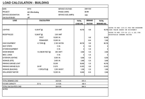
Section 220.43 covers the demand factors for both show windows and track lighting. This is very important to remember as show windows are present in nearly all retail stores that have window fronts. Here we don’t have a reduction for larger installations, just a flat figure per linear foot of the units.
In other than dwelling units, we consider loads associated with the receptacles. To do this, remember we calculate these at 180 VA per receptacle yoke [Section 220.14(I)]. Starting with this number, take the number of receptacles to get a total VA for the receptacle load and then we take the first 10,000 VA at 100%; then any receptacle loads over 10,000, we are allowed to use a 50% demand reduction. Remember that in the last article, we discussed in 220.14(K) (which deals with banks or office buildings) that we have to use the larger of two methods to get our total receptacle loads. Once we have our total receptacle load we can apply the demand allowances.

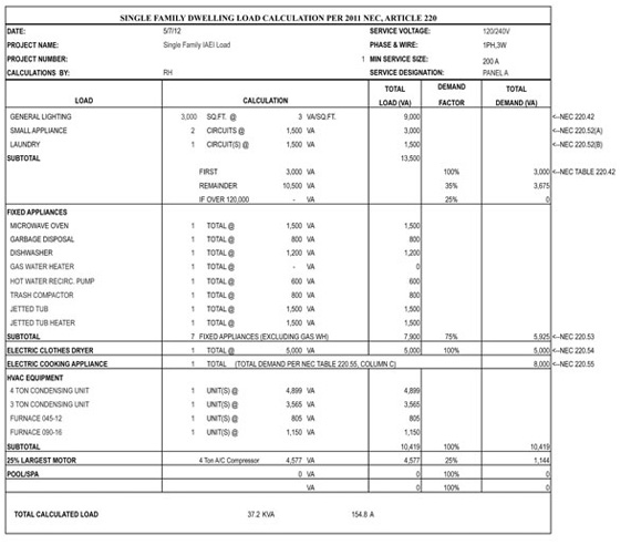
Figure 1. This is a residential load calculation, courtesy of Wright Engineers. Please note the code references to the right.
Motor loads will be added into our calculations as mentioned in 220.50, using Articles 430 and 440. In 220.51 we learn how to add in fixed electric space heating; in a nutshell, we just add these in at 100 percent.
We move on to 220.52 through 220.56, which specifically deal with dwelling units only. These items are to be taken on top of the general lighting loads calculated from the square footage and reduced for demand factors. We start out addressing the small-appliance circuit load, for which we know from 210.11(C)(1) that we have to have a minimum of two small-appliance circuits; these are to be added in at 1500 VA per circuit. So if we have the minimum of 2 circuits that would be 3000 VA, 3 would be 4500 VA and so on. Some of the larger custom homes have had up to 4 or 5 small-appliance circuits. Next, we address the laundry circuit, and again it is taken at 1500 VA per circuit. Remember this is the general laundry circuit. If you have an electric dryer, we add that on top of this figure. In 220.54 we have the requirements for electric dryers; we generally just use 5000 VA for the dryer in single-family dwellings.
The next item in dwellings to consider is appliances, which include such items as dishwashers, trash compactors, water heaters, garbage disposals, built-in appliance centers, built-in microwaves, instant hot water dispensers, warming drawers, and wine coolers. The key issue with these is that according to 220.53, if these are fastened in place then we take each of these at the load rating of the factory label and add them to our calculations. There is one bit of help, which is if you have 4 or more of these, then you can apply a 75% demand factor to the sum of the devices. The thinking is that you aren’t going to be running more than three at one time. During the plan submittal stage of a dwelling unit, the exact label information is hard to come by as the appliances have not usually been selected, at least not the exact model and options, so we often have to use some approximate numbers here based on cut sheets of what is expected to be utilized. One thing to keep in mind is if any of the equipment is gas instead of electric, then we simply note “gas” next to those items during a load calculation.
The next items for dwelling units are the calculations for electric clothes dryers and ranges or other cooking appliances. The most common practice here is an automatic 5000 VA figure for the electric dryer, and the base figure of 8000 VA for the electric oven/range. Again, this is the standard starting point for electric cooking units; however, if you know the exact loads and they fit into the allowances of Note 3 in Table 220.55, you may also use this method of calculation. For single-family dwellings, we seldom see anything other than the standard 8000 VA figure. However, when we get out of the single-family world and start to look at multi-family, then the 75% appliance factor and Tables 220.54 and 220.55 provide demand factors which will reduce the size of the main service, again based on the concept that not every tenant will be using every device at the same time as other tenants. This becomes a huge advantage when dealing with high-rise condominiums, for example, where you may have 100 occupancies or more. For dryers, if you have 43 or more in the facility, then we only use 25% of the value for sizing the service; electric ranges between 3.5 and 8.75 KW would use a 16% figure for more than 60 units.
Enough on dwellings for now, let’s move on to other occupancies. Section 220.56 addresses kitchen equipment in other than dwelling unit(s). This is directed toward commercial kitchens that utilize commercial electric cooking equipment. Commercial food service facilities have a high number of different devices. To name a few: deep fryers, ovens, cooktops, warming drawers, heat lamps, warming heaters, dishwashers, flash heaters for some dishwashers, microwaves, soup-pots, steam tables, refrigerators, freezers, and so on. Performing inspections in kitchens is always a time consuming and tedious procedure, you have to look at each piece of equipment separately, review the load requirements, the disconnecting means, proper access to the electrical panels, etc. However, here we are only concerned with the load calculations for those units, and we are referred to Table 220.56 which has demand figures depending on the number of pieces of electrical equipment to be used. As you can see from my list, it isn’t too hard to get to the chart maximum of 6 or more units, and at that number a 65% demand factor can be applied. Often times equipment is not always delivered according to the approved plans or load calculations; for instance, a piece of equipment that was originally shown as a gas unit gets changed to electric, or equipment gets added without the knowledge of the design professional. I’ve even connected equipment that was shown as gas and the bottom cooking surface was gas; however, the upper portion of the clamshell style grill was electric. My main point here is that commercial kitchens are electrical pigs and we have to be very thorough during the plans check, load calculations and inspections process.

Figure 2. Commercial load calculation, courtesy of Wright Engineers.
The next section 220.60 deals with non-coincident loads. The language states that where it is unlikely that two or more non-coincidental loads will be in use simultaneously, then it will be permitted to only use the larger of items for calculating the load. To me, this concept is pretty simple but let’s explore some examples. First, if you have an air-conditioning unit which only provides cooling and you use electric baseboard heat for your heating source, then you only need to add the one with the larger electric demand for the purpose of load calculation. Along the same line, when I first started doing electrical work in Las Vegas, several of the older houses had air-conditioning units which were not heat pumps units. They were straight cooling and had electric resistance heat strips for heating, so when we did the load calculations you had to know the size of the strips which are rated in kW, and then compare that load to that of the AC compressor and the outdoor fan. With that information, we would only use whatever the larger one was for sizing the service. I have to add in a note here regarding heat-pump units; these are air conditioners which use the compressor and coolant gas for both heating and cooling. They do this by reversing the direction of the refrigerant. Often these heat-pumps will also have electric resistance heat strips for emergency heating assistance in extremely cold conditions. From my experience, some of these utilize both the heat strip and compressor so you have to take the total load into account. These units often have labels for the minimum circuit ampacity with several options which the installer is to check when the resistance heater strip is added in. Once this is checked, it now gives you the new information to use for loads, wire size and overcurrent protection.
The sizing of the neutral for the service or feeder is addressed in 220.61. If you read this, it will probably just confuse you like it does the rest of us. So let’s think about the neutral. If you have any piece of equipment for which the main consumption of power is has very little or no phase-to-neutral load, then why do we need to have the neutral sized equal to the ungrounded conductors? The equipment which typically falls into this area are ovens, ranges, and dryers. So the code states we can do a 70% factor for sizing the neutral for the loads associated with these types of equipment. That seems like a lot of calculation, so I will share what typically happens instead. Usually the neutral is two wire sizes smaller than the ungrounded conductors; so as an example, a 200-amp residential service could have 4/0 AWG aluminum ungrounded conductors and a 2/0 AWG neutral. If no 240-volt loads are in a dwelling, then the code tells us in 220.61(A) the neutral has to be sized for the maximum net calculated load between the neutral and any one of the ungrounded conductors, which means it must be equal to the ungrounded conductors.

Photo 2. “This is a good example of one of the new modern high rise projects now being constructed”
Part IV of Article 220 deals with optional feeder and service load calculations. Because these articles are based on general information for combination inspectors, I won’t be going into any details on these methods as they are pretty specialized according to the type of occupancy and how to handle existing loads. Please take a moment to review these, since in some parts of the country they are used. For decades they were not allowed in Clark County, Nevada, due to the heavy use of cooling equipment; however, they have started to allow them with a modification requiring a 100% factor for A/C loads.
The last part of Article 220 is Part V which deals with farm loads — buildings and other loads. Here we address how to size the services or feeders for a farm dwelling, which is the same as we did for other dwellings. However, if we share the service or feeder with other farm buildings, then we have demand factors that may be applied. Again, this is not in the common realm of work performed by a combination inspector, so if this may apply to you, please review.
I also recommend reviewing the example of load calculations pictured here, as it provides an actual view of what we have described within this article. In the next article, we will cover Article 225, Outside Branch Circuits and Feeders.


Find Us on Socials