Harsh Environment—No Maintenance
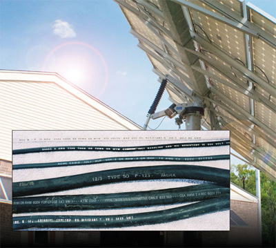 PV modules may be generating energy for 40–50 years after installation. While power production may not be what it was when the PV system was new, hazardous amounts of voltage and current will be still available from the PV array. The rooftop, outdoor environment is harsh. Unlike HVAC equipment, which requires periodic inspections and maintenance, PV modules and the rooftop wiring and equipment may not be examined for the life of the system.
Inspectors and plan reviewers need to be aware of the requirements for cables used in PV systems. They also need to know that the system longevity may impose stringent workmanship and materials requirements on the conductors in a PV system.
Conductors interconnect the modules to the PV direct current combiners (where used) and then to the disconnects, inverters, and eventually to the utility grid or other load. The outdoor environment the conductors are exposed to is one of the most strenuous for any electrical circuit found in premises wiring. In various parts of the country, module and source circuit conductors, both in and out of conduit are exposed to temperatures from -50°C (-58°F) to +80°C (176°F), continuous submersion in water (in some conduits), ice, wind, hail, snow, sand, and for conductors exposed to the sun, ultraviolet (UV) radiation.
For these conductors to survive in this environment for the module life of 40–50 years, the conductors must be properly selected and installed. Cables come in many types, sizes, and constructions and PV even has some unique cable types that are not available to other industries.
USE-2
For many years, USE-2 has been the conductor of choice (and metNECrequirements) for a durable cable that could be attached to the PV module and also field installed in the outdoor environment. It is suitable only for module and source circuit wiring on grounded PV arrays where one of the dc circuit conductors is connected to earth/ground. This direct burial cable is typically made with cross-linked polyethylene insulation. The cable has undergone a 350 hour accelerated UV test, but is not marked “Sun Light Resistant” even though it is considered suitable for the outdoor environment. USE-2 is rated for wet environments (it is a direct buried cable) and for temperatures up to 90°C. Without any other markings (such as a dual USE-2/RHW-2 marking), USE-2 has no flame or smoke retardants and may not be used indoors in conduit. The author has personally had USE-2 conductors made with cross-linked polyethylene insulation exposed in the harsh outdoor conditions of New Mexico for more 30 years without obvious signs of deterioration.
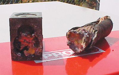
Photo 1. Lug is not suitable for fine-stranded cable.
PV Cable/PV Wire
PV modules are made for international markets and have attached conductors that can be used in different countries. Most of the rest of the world (ROW) uses transformerless inverters (a.k.a. non-isolated inverters) and ungrounded PV arrays (no dc circuit conductor, either positive or negative connected to earth/ground). TheNational Electrical Code(NEC) allows ungrounded arrays to be installed in the U.S., and a “PV cable” or “PV wire” is required for the permanently attached modules conductor as well as for the field-installed exposed wiring. This specialized conductor is only mentioned in the NEC in Section 690.35 and is not found elsewhere in the Code. It has a nonstandard outer diameter, so the conduit fill tables may not be used. It may be used on modules in ungrounded PV arrays and also on modules intended for grounded PV arrays. PV wire/PV cable is tested, certified and listed to Underwriters Laboratories (UL) Outline of Investigation 4703.
UL 4703 establishes the materials that can be used in the conductor and the tests that the conductor must pass. The conductor insulation may be either thermoset (synthetic rubber-like cross-linked polyethylene) or thermoplastic (PVC).
The thickness is specified and there may be one or two layers of insulation. The insulation must pass an accelerated UV test of 720 hours and will be marked “Sunlight Resistant.” PV cable/PV wire also has smoke and flame-retardants and may be used inside conduit inside buildings. In the U.S., it should not be called a “double-insulated cable” as that is a purely European term.
All Insulations Are Not Equal
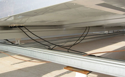
Photo 2. Improperly secured conductors can abrade and fault.
Both USE-2 and PV cable/PV wire are available with colored insulations (e.g., white, red, green), but care should be exercised when considering colored insulations. While these colored cables are marked “Sunlight Resistant” and have passed the 720-hour accelerated UV test, they do not have as much carbon black in them as do the black-insulated cables. Carbon black is one of the main insulation components that provides a conductor with UV radiation resistance. Cables with less carbon black may not fare as well over 40–50 years in the extreme PV environment as cables with high levels of carbon black.
And, in a similar manner, PVC insulated cables have passed the 720-hour accelerated UV tests, but PVC insulated electrical components like PVC jacketed UF cables and PVC liquid-tight non-metallic conduit (LFNC) have not survived well in the hot, sunny southwest outdoor environment.
In Conduits
Conductors in conduits are somewhat protected from the mechanical abuse that affects the exposed conductors. However, PV systems are experiencing ground faults in conductors in conduits indicating that more care must be exercised during the installation process. Not using the correct number of pull boxes and installing too many degrees of turn, as well as not installing bushings at the entry and exit points can lead to insulation damage. And, while the problems may not show up at system turn-on, they may show up in later years as the conduits are subject to thermal expansion and high temperatures from solar heating. Inspectors need to keep vigilant for signs of improper cable installation such as missing bushings, tight or stretched cables, and slivers of insulation.
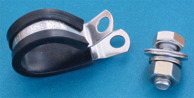
Photo 3. Stainless steel/EDPM Loop Strap (available from McMaster-Carr)
Conductor Stranding
The UL 4703 specification allows both normal class B stranding (typically 7–19 strands) and it also allows finer stranding which can be hundreds of fine strands in a 10 AWG conductor. The European IEC Standard for PV cable (yes, unfortunately, the same name) requires that the European PV cables be fine-stranded. While fine-stranded, flexible cables pose no problems when installed on the modules in the factory, the use of fine-stranded flexible cables is problematic where field-installed cables are involved. This is due to the lack of suitable terminals for fine-stranded cables (see photo 1). See NEC 110.14, 690.31(F), 690.74 and the “Perspectives on PV” article in the January/February 2005 IAEI News.
Excellent Workmanship Required
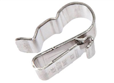
Photo 4. ACME cable clip by Wiley Electronics
TheNEC, in Section 110.12, requires that electrical equipment be installed in a neat and workmanlike manner. ANSI/NECA 1-2006 Standard Practices For Good Workmanship in Electrical Contracting provides details. However, both theNECand the NECA standard were developed for conventional electrical installations where the conductors are installed in either interior locations (modest temperature, low mechanical stresses) or in exterior conduits. The exposed PV conductors, as noted above, are subject to far less benign conditions, and those conditions will affect the cables for many decades. When it comes to the workmanship associated with these exposed PV source circuit conductors, that workmanship must be excellent, not just good. Winds blowing a slightly loose conductor against a PV racking member can cause the insulation to be abraded in a few short months, leaving a potential shock hazard or ground-fault hazard (see photo 2). Exposed module conductors that hang below the modules and touch the roof are also subject to abrasion on the roof surface. In colder climates, they are also subject to ice dams and frozen snow sliding down the roof separating the cables from the modules—not a desirable situation.
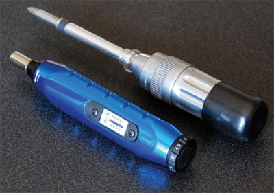
Photo 5. Torque screwdrivers
The use of the common black plastic wire ties that are rated as UV resistant do not survive the PV environment which exposes the plastic to high levels of UV radiation and high temperatures on a day-in, day-out basis for many years. The most common size of these wire ties is ⅛” to 3/16″ wide and these have failed in PV installations after only a few years. It is possible that the more robust units, ⅜”to ½” wide and thicker, would survive more years. My organization (Southwest Technology Development Institute) deals with the smaller size PV systems (3–18 kW) and we usually use EDPM rubber-cushioned stainless-steel loop clamps to secure the module wires (see photo 3). PV equipment suppliers also stock stainless steel ACME cable clips by Wiley and others (photo 4).
Terminations
In addition to securing the exposed conductors properly, these conductors and others in conduit must be terminated properly on the fuse holders, circuit breakers, combiners, disconnects, inverters and at other equipment. In most cases, screw terminals are used and on every piece of certified/listed equipment, there is a torque value that must be used. Section 110.3(B) of the NEC requires that all instructions and labels associated with a listed product be followed. A torque screwdriver or torque wrench must be used to make these connections (see photo 5). If these terminals are not properly tightened, they will fail (see photo 6). IAEI, IBEW, and NECA have demonstrated numerous times that the average electrician cannot accurately make a screwed electrical connection without the use of a calibrated torque device.
Inspectors: Maybe it is time for your chief to get some torque screwdrivers.
Summary
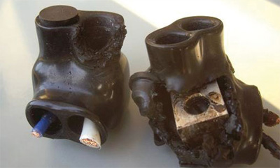
Photo 6. Improper torque results in failed connections
As the large number of PV systems being installed today age in the decades ahead, we will see the affects of “average” workmanship. Plan reviewers and inspectors rarely get to see a PV system that has been installed 5 or 10 years ago. Research and development people who test these aging systems see the signs of deterioration on nearly every system. Systems integrators who sell maintenance contracts with their systems are finding issues with the conductors as the systems age.
It might prove informative and educational for plan reviewers and inspectors to visit a few of these older systems and see how the conductors and other parts of the installation are holding up. Perhaps the workmanship standard needs to be moved from “Good” to “Excellent.”
For More Information
If this article has raised questions, do not hesitate to contact the author by phone or e-mail. E-mail: jwiles@nmsu.edu; Phone: 575-646-6105.
See the web site below for a schedule of presentations on PV and the Code. Call the author if you would like to schedule a presentation.
The Southwest Technology Development Institute web site maintains a PV Systems Inspector/Installer Checklist and all copies of the previous “Perspectives on PV” articles for easy downloading. A color copy of the latest version (1.93) of the 150-page, Photovoltaic Power Systems and the 2005National Electrical Code: Suggested Practices, written by the author, may be downloaded from this web site: <ahref=”http: www.nmsu.edu=”” ~tdi=”” photovoltaics=”” codes-stds=”” codes-stds.html”=””>http://www.nmsu.edu/~tdi/Photovoltaics/Codes-Stds/Codes-Stds.html
This work was supported by the United States Department of Energy under Contract DE-FC 36-05-G015149


Find Us on Socials