 Photovoltaic (PV) systems prices continue to drop and inspectors are getting numerous requests for inspections. The questions that I receive indicate that this is new territory for many inspectors. These questions also indicate a few “holes” in the National Electrical Code, which we hope to plug in the 2014 NEC.
Questions on Grounding
Question: Does the NEC require that a grounding electrode conductor (GEC) and a grounding electrode (ground rod) be connected to the new transformerless inverters? See photo 1. Section 690.47 in the 2011 National Electrical Code (NEC) does not exactly address this issue.
Answer: If the listed transformerless inverter (also called a non-isolated inverter) adheres to the requirements of Underwriters Laboratories Standard 1741 for PV inverters, the inverter will not even have a terminal for a grounding electrode conductor. These inverters are used with an ungrounded PV array. The UL standard requires a grounding electrode conductor terminal and the Code would require a grounding electrode conductor only when there is a bonding jumper in the direct current (dc) side of the inverter. In normal transformer-type of inverters (also called isolated inverters), this bonding jumper is part of the required 690.5 ground fault detection and interruption (GFDI) circuit.
Photo 1. Transformerless inverter. Looks like many other inverters that have transformers, but may not have a GEC terminal or a 690.5 Warning. Photo courtesy SMA Technologies
Transformerless inverters do not connect one of the dc circuit conductors in the PV array to ground (as allowed byNEC690.35) and have no internal bonding jumper. Therefore, there will normally be no terminal to connect the GEC to and theNECdoes not require a dc GEC. Unfortunately, Section 690.47 does not specifically say this, so a proposal has been submitted for the 2014NECthat hopefully clarifies the issue. Here is the wording of that proposal for 690.47(B).
Add a new third paragraph to 690.47(B) as follows:
Ungrounded DC PV arrays connected to utilization equipment with common ac and dc equipment-grounding terminals shall be permitted to have dc equipment-grounding requirements met by the ac equipment-grounding system without the requirement for a dc grounding electrode conductor or grounding system.
We have been asking PV installers to get that dc GEC connected to the inverter for many years. Now, on these new systems, it will no longer be required. But, be advised that not all inverter manufacturers, nor their certification agencies, will read all of the fine print in the standard and some transformerless inverters will have terminals or instructions for a GEC. This terminal will be, as it is in other inverters, connected internally to the dc and ac equipment-grounding conductor terminals. And, if desired, this terminal may be used with a GEC routed to a grounding electrode. This would essentially be a 250.54 optional grounding electrode and that electrode does not have to be bonded to any other grounding electrode. It is connected only to the equipment-grounding system in the inverter.
The 690.47(B) proposal for the 2014NECindicates that since the ac and dc equipment-grounding conductor terminals are common in the inverter, the ac equipment-grounding system (grounded at the service-entrance equipment) can be used to provide the array equipment-grounding function.
However, this may route lightning induced surges on the array equipment-grounding system through the inverter and into the service equipment. Far-thinking PV installers may elect to install optional 250.54 grounding systems at the array and possibly also at the inverter to better protect against these surges.
Question: What is the proper method of grounding the modules and microinverters that are not manufactured or certified/listed as an AC PV module?
Answer: These microinverters are essentially small inverters. It is difficult to precisely define them as a unique device since they are continually getting larger (now 380+ watts) while some normal “string” inverters are down to 700 watts and below. The micro-inverter/ PV module combination has many of the characteristics of any other inverter when it comes to grounding. There are usually exposed metal surfaces on both the inverter and the module that must be grounded (i.e., connected to earth through an equipment-grounding conductor/system). The microinverter may cause the module to operate as an ungrounded module, as a positively grounded module (most common), or as a negatively grounded module. This form of grounding refers to how the dc circuit conductors are referenced to ground and is called system or functional grounding. When the module is operated in a grounded manner, there will be a dc bonding jumper inside the inverter and this fact will require that the inverter have a dc grounding electrode conductor terminal. The dc grounding electrode conductor (GEC) will have to be 6 AWG in exposed locations and at least 8 AWG inside conduit. It will have to be unspliced or irreversibly spliced from the microinverter all the way to the grounding electrode or the grounding bus bar in the equipment that has a connected grounding electrode.

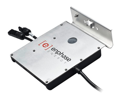
Photo 2. Microinverter with single grounding terminal for both equipment grounding and dc grounding electrode conductor connections. Photo courtesy Enphase.
The inverter should also have an ac equipment-grounding conductor that will be routed with the ac output circuit conductors. With a dc input from the module, there should also be provisions to accept a dc equipment-grounding conductor from the PV module. However, in many cases, a single external terminal on the microinverter can meet both the equipment-grounding terminal requirements (ac and dc) and the grounding electrode conductor terminal requirement. See photo 2
In general, the module will require an equipment-grounding conductor attached to the frame following the instructions provided in the module instruction manual and sized per 690.45. In many cases this can be as small as 14 AWG. Of course, 690.46 may apply or the AHJ may require a larger conductor to provide greater mechanical integrity. In these cases, a 6 AWG conductor is frequently used.
In some cases, an electrical connection (not just a mechanical attachment between inverter and module frame) between the module frame and the microinverter enclosure will enable a single equipment-grounding conductor to be used for both devices.
Creative sizing (6 AWG) and routing of a single unspliced conductor can be used to meet all module and microinverter grounding requirements.
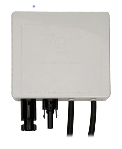
Question: What type of grounding is required on modules with plastic frames (also known as industrial composites) and these new dc-to-dc converters that are attached to the module outputs that have plastic enclosures? See photo 3
Answer: My favorite type a question — an easy one. If there are no exposed metal parts on a module, a microinverter, or a dc-to-dc to dc converter, there will be no requirement for an equipment-grounding conductor and probably no place to attach such a conductor. However, we may get a plastic encased dc-to-dc inverter or a microinverter that has a dc grounding electrode conductor requirement and there will be a terminal for that conductor. The manual for these certified/listed products will have the instructions for this connection.
Questions on Overcurrent Protection
Question: When do multiple strings of modules require a fused combiner box or a set of fuses inside the inverter?
Answer: The number of strings of PV modules that can be connected in parallel without a fused combiner is determined by the short-circuit current (Isc) rating of each module and the maximum series fuse. Each string of modules can, under worst-case conditions of sunlight, generate 1.25 x Isc of current into a fault in a parallel-connected string of modules. If we have “n” strings connected in parallel, then “n-1” strings can send fault current into a faulted string. The total fault current would be (n-1) x 1.25 x Isc. That fault current must be less than the rating of the module protective fuse marked on the back of the module. If the fault current were greater than the value of the module protective fuse, then the module and its cable could be damaged where there was no fuse.
A little PV math shows that:
(n-1) x 1.25 x Isc < F where F is the value of series fuse marked on the back of the module.
If we solve this for n, the total number of strings in parallel, we get:
n< (F+1.25 x Isc)/(1.25 x Isc)
Example 1: Module W has an F of 15 amps (pretty common) and an Isc=8 amps.
n<(15+1.25 x 8)/(1.25 x 8) = 25/10 = 2.5, and the total number of strings (n) for this module can be 2.5; and since n has to be a whole number, two strings of modules can be connected in parallel.
Example 2: Module Y has F = 20 and Isc = 3. n < (20+1.25 x 3)/(1.25 x 3) = 23.75/3.75 = 6.33 and six strings of these modules can be connected in parallel.
For many PV modules in the 180–300 watt range, only two strings can be connected in parallel because of these constraints.
Question: Can two sets of 15 microinverters be connected in parallel without overcurrent devices?
Answer: In short — No. The microinverters are tested and certified/listed to be used as a set with the cable or wiring harness provided with them. The instruction manual will specify how many microinverters can be connected to the factory cable and the rating of the required circuit breaker for that set on a single cable. This is consistent with NEC 705.12(D)(1) that requires a dedicated circuit breaker for utility-interactive inverters.
Question: How does the short-circuit current from a PV module affect the output current of the connected dc-to-dc converter? How is the PV module open circuit voltage used to calculate the voltage rating of any combiner or inverter downstream.

Photo 3. Dc-to-dc converter. Photo courtesy Tigo Energy
Answer: This new technology of dc-to-dc converters and other PV module power processors has evolved in numerous configurations. Some converters are required on the output of every PV module; some are required on only a few modules. Most are connected in series, but some are connected in parallel. Some of the devices are “smart” and must be used with “dumb” inverters. All of these devices must be certified/listed to UL Standard 1741. There are and will be too many variations to address the specific connection requirements of each product in the NEC directly. The outputs of these devices are decoupled from their inputs, so PV module short-circuit currents and voltages cannot directly be used to meet any Code requirements that are associated with the circuits connected to the output of these devices. Essentially the installers and the inspectors will have to rely on 110.3(B) where these certified/listed devices must be installed following all instructions provided with the product and all labels on the product. A proposal for the 2014NECwill reinforce this requirement in Article 690.
Questions on Large Systems
Question: What needs to be addressed concerning the ground-fault protective device connected to the inverter output to meet the exception on 690.64(B)(3)/705.12(D)(3)? The exception requires that loads be protected from all sources of ground-fault currents.
Answer: This particular area is beyond the scope of the NEC. The load circuits must be protected from ground faults originating from the utility service and also from ground-fault currents originating from the load-side connected PV inverter. The fault currents reaching the load circuits will be shared between these two sources. It would take engineering analysis to determine how the two sources will share the fault currents under various situations and how the settings of each ground fault device will be determined.
Question: The service disconnect is at 12 kV (12.47 kV) for a large facility and the PV system will be connected at 480 volts on a feeder. For this load-side connection, how do we apply 705.12(D)(2) to determine conductor and busbar ampacities when transformers are involved?
Answer: The voltage ratio of the transformer is used to adjust the various overcurrent device ratings and ampacities to an equivalent set of numbers at a single voltage, either at the 12 kV or the 480 V level.
For example, a 25-amp fuse on the 12 kV side of the transformer would translate to about a 650-amp (25 x 12470/480) overcurrent device when referenced to the 480 V feeder. Then the requirements of 705.12(D) may be applied. In these large facilities, keep in mind that the PV inverter output connection to the existing system must be made at the end of a feeder or busbar opposite the utility feed end before the 120% allowance can be used. If the sum of the overcurrent devices exceeds 120% of the ampacity of the feeder or the rating of the busbar, or the PV connection cannot be properly located, a 100% factor must be used. Any circuits (conductors and busbars) not protected by a single overcurrent device that may carry current from the PV system may have to be increased in size.
Keep those questions coming. The holes in the 2014 NEC have not yet been addressed and thatCodeis more than two years away.
For Additional Information
See the web site below for a schedule of presentations on PV and theCode.
The Southwest Technology Development Institute web site maintains a PV Systems Inspector/Installer Checklist and all copies of the previous “Perspectives on PV” articles for easy downloading. A color copy of the latest version (1.91) of the 150-page, Photovoltaic Power Systems and the 2005 National Electrical Code: Suggested Practices, written by the author, may be downloaded from this web site: http://www.nmsu.edu/~tdi/Photovoltaics/Codes-Stds/Codes-Stds.html
And yes, it may be updated to the 2008 and 2011 Codes sometime this year.


Find Us on Socials