 Apparently, we do. However, there is no reason to generalize this problem. Although there might be problems (or rather challenges) for the code users in understanding of some requirements related to the selection of conductors, I’ll concentrate on two specific issues that have apparently become a source of confusion:
1. Introduction of Rule 4-006 into the CE Code; and
2. Recent UL/ULC Public Notice release 12PN-51.
So, let’s concentrate on each of these subjects separately.
Our first issue is introduction of Rule 4-006 into the CE Code. Why now?
In order to clearly follow the sequence of events, we need to “unearth” a few relevant bits of history. A number of years ago, the NEC/CEC Ampacity Task Force had been established.
This Task Force was charged with the responsibility to conduct a thorough review of the ampacity values of the NEC Tables 310.16 and 310.17 and the CEC Tables 1–4, and to harmonize these values in both Codes. The reason for such assignment was based on a need to re-calculate the ampacities used in both Codes in accordance with the objective scientific formula and to facilitate necessary changes to both Codes that would prevent excess of the maximum allowable operating temperature at any connected termination. There are many pieces of electrical equipment (fused switches, circuit breakers, panelboards, etc.) that have been tested, marked (and certified to the harmonized bi-national: UL/CSA) product standards based on the maximum permitted operating temperature at 75⁰C.
This fact has been captured by the NEC for quite some time. Article 110.14(C) of the NEC mandates temperature limitations at such termination and requires use of conductors being sized on the ampacity values in 75⁰C column of Tables 310.16 and 310.17.
Until 2012 edition of the CE Code, there was no similar requirement in the CEC, as the previous values of ampacity tables of the CEC were more conservative than in the NEC, and no temperature imitation at conductors terminations were deemed to be necessary. Therefore, users of the CE Code have been routinely selecting conductor sizes based on 90⁰C column from Tables 1–4 for termination on the equipment that is marked for the temperature restrictions up to 75⁰C.
However, after the assignment—to correlate ampacity values had been completed by the NEC/CEC Ampacity Task Force, all values of the NEC Table 310.15(B)(16) [formerly Table 310.16] and 310.15(B)(17) [formerly Table 310.17], and the CEC Tables 1–4 have been harmonized.
The result of such harmonization is seen in both Codes. The 2011 edition of the NEC and 2012 edition of the CEC have absolutely identical ampacity values in these respective tables. If we now compare the ampacities values between 2009 and 2012 editions of the CEC, we’ll see that in the latest edition of the CE Code these ampacities (particularly in 90⁰C column of Tables 1– 4) have been significantly raised.
It is obvious now that the restrictions mandated by Article 110.14(C) of the NEC have to be reflected in the CEC—to prevent unsafe operating temperatures at the point of termination of the conductors to the equipment that is marked with the temperature limitation.
New Rule 4-006 of the CE Code states this requirement as follows:
“4-006 Temperature limitations
(see Appendix B)
“(1) Where equipment is marked with a maximum conductor termination temperature, the maximum allowable ampacity of the conductor shall be based on the corresponding temperature column from Table 1, 2, 3, or 4.
“(2) Where equipment is not marked with a maximum conductor termination temperature, 90 °C shall be used by default.”
Appendix B Note on this Rule provides additional clarification on this requirement:
“Appendix B Note on Rule 4-006
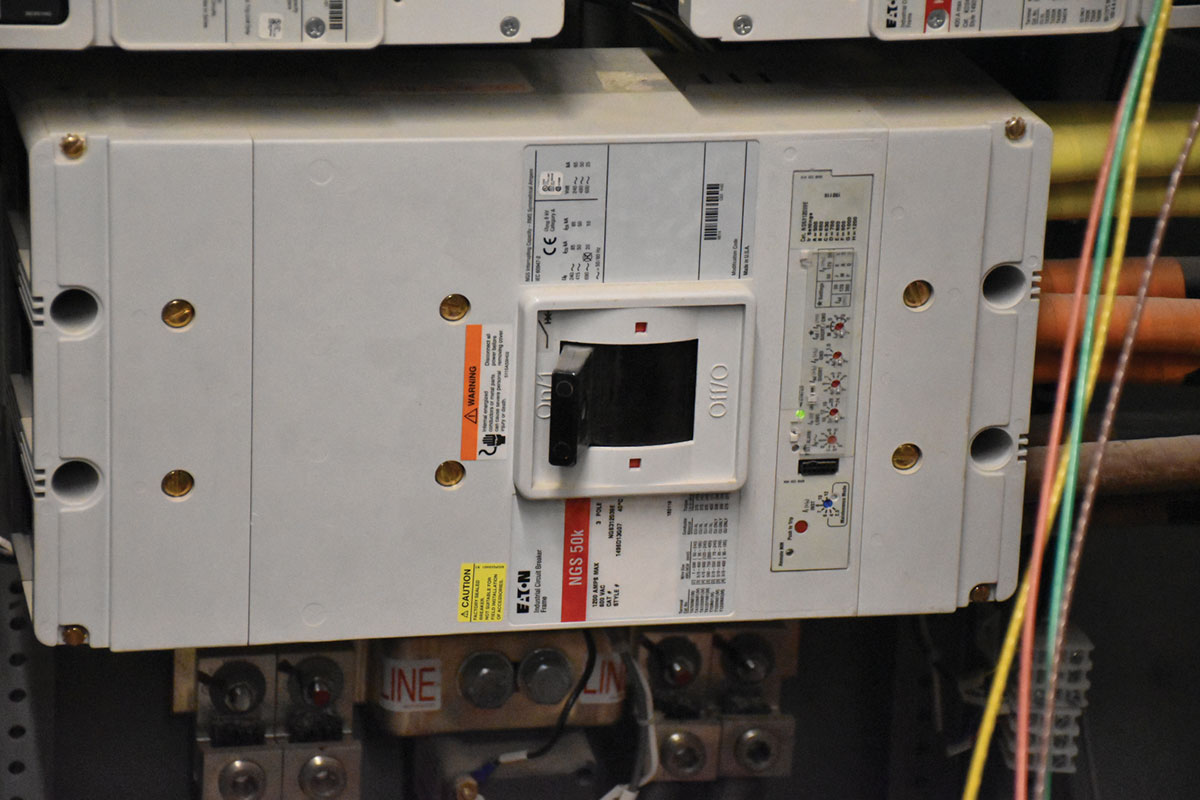
“The intent of this Rule is to correlate the temperature rating of conductors where the ampacity is selected from Tables 1 to 4 with the lowest temperature rating of electrical equipment or any wire connector (terminal connector, lug, etc.). It is intended by this Rule that the ampacity of conductors be selected from the temperature column in Table 1, 2, 3, or 4 that corresponds to the temperature rating marked on the electrical equipment. As an example, where a conductor is terminated on a breaker with a 75 °C rating, the maximum conductor ampacity would be based on the 75 °C column of the Tables. It should be noted that the temperature rating of a wire connector (terminal connector, lug, etc.) that is connected to the equipment may be higher than that of the equipment itself; it is the equipment rating that determines the conductor size, not the lug.”
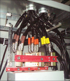
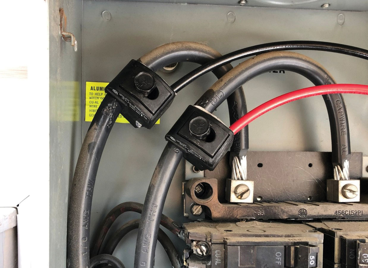
So, based on the requirement of Rule 4-006 and on the clarification Note on this Rule, it appears to be clear that the conductor ampacity should be selected from the temperature column that is consistent with the maximum allowable operating temperature of equipment to which that conductor is intended to be terminated.
But, what if a RW90 conductor is readily available and is intended to be used by a contractor? Could we use the ampacity value from the 90⁰C column and apply some de-rating factors of Tables 5A–5C? From the discussions on this issue between the designers, electrical contractors and regulators, it appears that there is some confusion in relation to this particular point.
Nobody would argue that a typical RW90 conductor could not be selected, but the ampacity of this conductor would now have to be selected from 75⁰C column of Tables 1–4 of the CE Code.
So, why can’t we select ampacity for a RW90 conductor from the 90⁰C column of a respective ampacity Table and to apply one of the correction factors of Tables 5A–5C?
Correction factors of Table 5A, 5B, and 5C are intended only for the allowable ampacity values obtained from Table 1, 2, 3, and 4.
It should be noted that for equipment with a conductor termination rating of 75⁰C, Rule 4-006 requires the allowable ampacities to be “based” (i.e., to be obtained) on the 75⁰C column of Table 1, 2, 3, or 4. The Rule does not permit basing the allowable ampacity on any other value than the value obtained from the 75⁰C column for equipment with a required conductor termination rating of 75⁰C.
The rationale for Rule 4-006 was to recognize how the equipment was tested during the certification process.
If we’ll review the CSA standards C22.2 No 4 Enclosed and Dead-Front Switches; C22.2 No 5 Molded-Case Circuit Breakers; Molded-Case Switches and Circuit-Breaker Enclosures; C22.2 No 29 Panelboards and enclosed panelboards and C22.2 No 244 Switchboards, we’ll find that all these standards require the conductor used during the temperature testing to be based on a 75⁰C ampacity.
The maximum allowable operating temperature of any circuit should be always limited to the lowest permissible value of such temperature for any component of the circuit.
In a practical sense, a conductor ampacity is the operating temperature for a conductor that is fully loaded to the applicable values in Tables 1, 2, 3, and 4, and this ampacity would be equal to the temperature rating of the conductor.
For example, if 4X350 kcmil copper conductors rated at 75 degrees C are installed in four raceways at an ambient temperature of 30⁰C and loaded to 1200 A, the operating temperature of these conductors would be 75⁰C. If we would select the 90⁰C rated conductor for the same example, the operating temperature of the conductor would be also 75⁰C.
If, in another example, 3X#3 RW90 conductors in a raceway are loaded to 115 A in accordance with Table 2 of the CEC, then such conductor loading would result in a conductor operating temperature of 90⁰C.
When the number of #3 RW90 conductors is increased (let say to eight conductors), Table 5C would require a correction factor of 0.7. In this case, 115 A x 0.7 = 80.5 A. Therefore, each of these 8X#3 RW90 conductors loaded to 80.5 A will again operate at the temperature of 90⁰C.
To limit the operating temperature of the conductor to 75⁰C (the maximum allowable temperature rating of the equipment) the ampacity would need to be selected from the 75⁰C column, and then the correction factor of Table 5C should be applied to the selected ampacity. In the example of 8x#3 RW90 conductors in the raceway (from the 75⁰C column of Table 2 and from Table 5C) 100 A x 0.7 = 70 Amp. Therefore, each of these 8X#3 RW90 conductors loaded to 70 Amp will again operate at the temperature of 75⁰C.
The main issue here is the effect that the operating temperature of the conductor has on the equipment to which this conductor is connected. The conductor can handle the ampacity, but the equipment was not tested with terminations above 75⁰C.
If, in addition to the discussion above, the selected 3X#3AWG RW90 conductors are terminated at the equipment rated at 75⁰C, and these conductors are operating in the ambient temperature exceeding 30⁰C, then the appropriate de-rating factor of Table 5A should be applied to the ampacity already selected from the 75⁰C column. If, for example, the ambient temperature is 40⁰C, then 100 A ampacity must be multiplied by the correction factor 0.91 from Table 5A, as the actual conductor used in this example is RW90 (and not RW75). Therefore, each of these 3X#3 RW90 conductors would be now loaded to 100 A x 0.91 = 91 A, and these RW90 conductors will again operate at the temperature of 75⁰C.
And, of course, regardless what correction factors are used for the selected ampacities, the resulting (decreased) ampacity of conductor should be checked for compliance with Rule 8-104 to ensure that it is not less than 125% of the calculated load.
Let’s now discuss the second issue – Recent UL/ULC Public Notice release 12PN-51.
UL and ULC have recently published the following notice. (However, from the perspective of application of this notice for the Canadian electrical industry, the discussion is limited only to the ULC portion of this notice).
“UL and ULC announce important changes to certification programs (Release 12PN-51)
“UL has recently conducted research on a wide array of current products and systems originally certified under UL 2196, Tests for Fire Resistive Cables and ULC-S139, Standard Method of Fire Test for Evaluation of Integrity of Electrical Cables and determined that they no longer consistently achieve a two-hour fire-resistive rating when subjected to the standard Fire Endurance Test of UL2196 or
ULC-S139. “Consequently, UL and ULC will not be able to offer certification to the currently existing program related to these standards.
“As a result, manufacturers are no longer authorized to place the UL mark or ULC mark on the following products:
“UL Classified Fire Resistive Cable (FHJR)
“ULC Listed Fire Resistant Cable (FHJRC)
“UL Listed cable with “-CI” suffix (Circuit Integrity)
“Furthermore, UL has removed from its certification directory all Electrical Circuit Protective Systems constructed with Fire Resistive Cable (FHIT).”
This notice has created a significant adverse impact on all electrical safety stakeholders, and particularly on the manufacturers of wiring products and on the electrical designers, and has become a subject of confusion in the electrical industry.
It appears from the early UL generic letter to the manufacturers of wiring products that UL (and in Canada – ULC) has published the attached public notice based on concerns that certain wiring products (which in addition to being designed, constructed, tested and certified to the applicable CSA Part II standards), are designated as “fire resistive cables” after being tested to the ULC standard S139, may, in fact, no longer conform to the ULC S139 circuit integrity test.
Apparently, some of such cables have failed the ULC S139 test, when they are installed in a metal conduit with the interior wall constructed with zinc coating, as at high temperatures a zinc coating may interact with copper conductors creating a brass alloy that melts at a lower temperature than copper conductors, thus impacting on the circuit integrity.
If the specific technical concern identified above is accurate (i.e., if it is limited to the melting of alloy inside the rigid metal conduit), the ULC following statement “manufacturers are no longer authorized to place the ULC mark on the following products: ULC Listed Fire Resistant Cable (FHJRC),” made in the referenced “Public Notice release” appears to be highly questionable, as the compliance with the circuit integrity test method described in the ULC S139 does not apparently require a certification monogram (in addition to the monogram signifying compliance of a cable with the applicable CSA safety product standard).
It is interesting to note that in accordance with Clause 6.1A of ULC S139 – the product shall be marked with the circuit integrity rating only, and not with the additional certification monogram. The ULC Notice indicating “ULC will not be able to offer certification to the currently existing program related to these standards” also appears to be questionable, as Clause 3.2.1 of the ULC S139 states the following: “Cables shall be installed in raceways or supports as permitted for that cable type by the Canadian Electrical Code.”
Based on this provision of Clause 3.2.1 of the ULC S139, each particular test assembly in accordance with this standard must reflect condition of use of a specific type of cable under relevant installation requirements of the CE Code. This means that if an armoured cable is being tested for circuit integrity in accordance with the ULC S139, such cable would not be tested in a raceway, as armoured cable is not intended by Table 19 of the CE Code to be used in raceway. Accordingly, if a typical communication, community antenna or Class 2 circuit cable would be subjected to the test in accordance with ULC S139, such test assembly would not have to include a raceway, as in accordance with the CE Code, communication, community antenna or Class 2 circuit cables are not specifically required to be installed in raceways. These examples clearly indicate that the technical concerns which prompted the ULC to publish the referenced notice would not be warranted for all test methods of the ULC S139, and that suspension of the certification of the circuit integrity tests to absolutely all types of test assemblies which are set up in accordance with Clause 3.2.1 of the ULC S139 to comply with the conductors installation requirements of the CE Code, is not necessarily warranted.
One of the main concerns with this ULC Public Notice relates to the fact that the compliance with the test methods for circuit integrity of conductors in accordance with the ULC standard S139 is mandated by the National Building Code of Canada (NBCC) and by the ULC standard S524 “Installation of fire alarm systems,” and both these documents are legally adopted for a regulatory purpose in the respective Canadian jurisdictions.
From a practical view point, the ULC Public Notice will leave the electrical industry practitioners with no other option, except for resorting to means for fire protection of conductors (required by the NBCC to be protected against exposure to fire) by encasing conduits containing such conductors in at least 100 mm of concrete.
This Public Notice appears to disregard the fact that a typical MI cable designed and constructed to very stringent requirements of the CSA standard C22.2 No.124 (which also incorporates provisions for fire rating) would not be allowed to be used for the purpose of complying with the NBCC 1 h or 2 h fire rating requirements, as Clause 6.7 of this CSA standard states the following
“6.7 Fire rating
“Cables marked in accordance with Clause 5.3 shall comply with the requirements of ULC-S139.”
It should be noted that the ULC is aware of the industry concerns, and hopefully this matter will be resolved, when this article is published.


Find Us on Socials