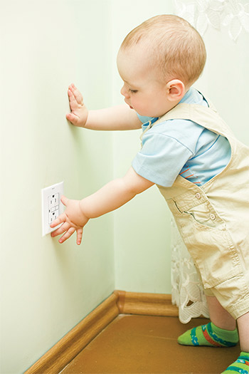
 In the last edition of this column, we reviewed the incredible receptacle and the standards requirements around these products. Well, I left out one important piece of the puzzle: the tamper-resistant receptacle (TRR). These devices deserve to be put on a pedestal, so to speak as they work every day to protect our future — those little bundles of joy who at times become intrigued by those tiny slots in walls that seem to demand the insertion of paper clips or just about any other object that may seem to fit. Tamper-resistant receptacles are a direct response to statistics of children who tried to do just that and ended up in the hospital.
Just as with any new requirement in our industry, many people question new technology and resist adoption of these types of requirements. The fact is that many new code changes are supported by statistics and data at their core; the TRR requirements are no different. This is why the TRR requirements have fared so well in those jurisdictions adopting the National Electrical Code (NEC). The data behind the requirements for these devices include U. S. Consumer Product Safety Commission (CPSC) data over a 10-year period that found more than 24,000 children under 10 years of age were treated in emergency rooms for receptacle-related incidents, and more than 10% of those children suffered severe shock and burns. An average of seven children a day suffered from some type of injury from electrical receptacles. Eighty-nine percent (89%) of those injured were under six years of age. Fifty percent (50%) of those injured were toddlers. It was very interesting to learn that the vast majority of these incidents occur in the home where, more than likely, children are under adult supervision.
These devices may be relatively new to residential structures but, the fact is, they have been around for decades; mandated in hospital pediatric wards since NEC 1981 as part of Section 517-90(b) “Pediatric Locations.” The language in this section required, “Fifteen- or 20-ampere, 125-volt receptacles intended to supply areas designated by the governing body of the health care facility as pediatric wards and/or rooms shall be tamperproof. For the purposes of this section, a tamperproof receptacle is a receptacle which by its construction, or with the use of an attached accessory, limits improper access to its energized contacts.” Over time, this section has changed including the removal of the “tamperproof” terminology. These devices are resistant to tampering, not impervious to the act.
 It was NEC 2008, as a part of Section 406.11, that introduced these devices as requirements for new and renovated dwelling units. As with every code change and it seems like every new safety provision, some resist local adoption of these types of new requirements. Even in light of opposition, the adoption of this provision has progressed quite well from state to state with approximately four states amending their requirement.
It’s All about the Shutters
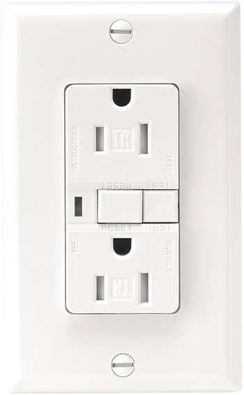
The main goal of a TRR is to provide a level of protection to help prevent a child from inserting an object into one of the blade openings of the receptacle. When you look at the face of a TRR, you will notice that the two blade openings have what appears to be a barrier. The round hole, the one that received the grounding pin of the plug, does not have a shutter. Touching or inserting an object into the round hole of a properly wired device is not advised, but because it is the ground reference point should not result in harm to the inserter, more than likely a very curious child. In a NEMA 5-15, 15-A 125-V device the two slots that have barriers are, of course, the hot and neutral (grounded) parts. The object of the design is to ensure that the act of probing with an object, let’s say a bobby pin, safety pin or other similar object, in any single slot does not successfully let it penetrate to the energized components internal to the device.
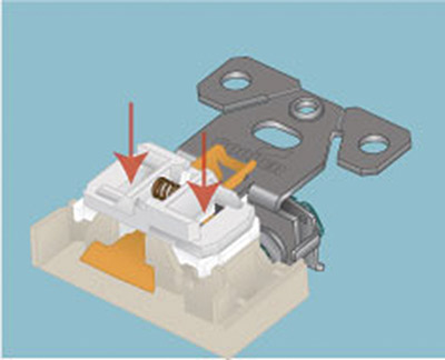
Insertion is permitted when both slots receive a blade at the same time. In a typical mechanism, inserting a plug compresses a spring, simultaneously opening both shutters. While insertion of an object in any single shutter will not open the device such that the shutter slides out of the way. This sophisticated approach to the shutters ensures that curious George does not successfully hit “pay dirt” and end up in the emergency room. Because these devices have a very important goal and are a bit more complex than the standard receptacle, the UL standard for receptacles was modified to include new requirements. Additional tests for the TRR are included in UL 498, “Standard for Safety Attachment Plugs and Receptacles.”

A Standards Perspective
So let’s peek under the hood and look at the standard requirements behind the products that entered the receptacle world of heavily used and often abused electrical devices.
UL defines this device as “A receptacle which by its construction is intended to limit improper access to its energized contacts in accordance with the National Electrical Code, ANSI/NFPA-70.” In true form for UL 498, “Standard for Safety Attachment Plugs and Receptacles,” tamper-resistant receptacles are subjected to performance requirements that go above and beyond those performance requirements for standard receptacles. The following performance criteria are additional items to those discussed in the last edition of this column.
1. Probe Test: This test starts fresh with twelve untested devices. A probe of specific dimensions, similar to that of a paper clip, is applied to each of the receptacle’s slot openings, at a force of 8 ounces. The test attempts to bypass the tamper-resistance mechanism by manipulation in the slots in any orientation. An indicator is wired to the probe and the wiring terminal of the outlet slot being tested to announce if contact is made. In addition, these devices are subjected to another set of probes for a period of 5 seconds at a force of 10 lbs., looking for a way to bypass the tamper-resistance mechanism.
2. Impact Test: This test uses six of the twelve devices used in the previous test and subjects them to either a ball-pendulum impact or a vertical-ball impact test which strikes the receptacle face or tamper-resistance mechanism or other. The test is trying to determine the ability of the tamper-resistant mechanism to withstand an impact and continue to function. The receptacle cannot crack and the tamper-resistant functionality cannot be compromised. The sphere used is 2 inches in diameter and weighs in at 1.18 lbs. For the pendulum test, the sphere is suspended by a cord and swung like a pendulum. It is dropped 51 inches and the impact is of a 5.0 ft-lb force. In the vertical impact test, the sphere drops from a height of 51 inches and impacts the center of each receptacle.
3. Mechanical Endurance Test: This test uses six devices that previously were subjected to the above probe test. In this test, a machine continuously inserts and withdraws — 5,000 times — an attachment plug having secured solid brass blades. The machine controls the velocity of the withdrawal and insertion; the blades, contacts and tamper-resistant mechanisms must not be adjusted, lubricated, or conditioned in any way before or during this test. After this test, these devices are tested again to ensure attachment plugs can be mated; probes cannot compromise the tamper-resistance ability, and it can perform for the dielectric voltage withstand test.
4. Dielectric Voltage Withstand Test: A TRR must withstand without breakdown, for a period of one minute, the application of a 60 Hz voltage of 1000 V plus twice the rated voltage rating of the receptacle. The devices used again are those previously used in the above tests.
As can be seen here, these devices are given no relief from a standards perspective; they must perform when called to do so.

This is an internal view of how both shutters must be acted upon to permit the blades of the plug to be inserted.
Field Performance
A question that often graces code adoption hearings and other similar venues is the question of insertion force. Inevitably, you hear about concerns of someone having difficulties inserting a plug into the receptacle. The presence of shutters and the lack of familiarity will understandably generate these types of concerns. As shown above, these receptacles do not undergo any additional testing beyond the standard receptacle with regard to insertion forces. If you recall from our last article on the receptacle, insertion force is covered as part of section 117.8 of the standard. This section performs conditioning on the receptacle and requires that the standard blade, which the Standard calls a “gauge,” assembled without the grounding pin and with the line blades without holes, be inserted into each outlet of the receptacle. The insertion forces are measured and must meet specified criteria. As per this requirement, forces must not exceed 40 lbf required to seat a standard gauge against the receptacle face. Again, this is the same requirement for a standard receptacle.
Insertion of plugs in the case of TRRs is physically achieved in the same manner as that for standard receptacles. There is no getting around the fact that some additional frictional forces are present when inserting plugs into these receptacles; the shutters do provide some additional resistance during the processes of insertion. The additional forces are not significant. Problems may arise, though, due to application issues due to various situations contributable to the misuse or abuse of these products. One good example of arguably a less obvious abuse is drywall sanding. There have been reported cases where receptacles present during the process of sanding by drywall finishers have experienced plugging of their shutters. These devices are no different from many other electrical devices and care should be taken during construction. Another example of where insertion may be impacted includes those times when plug blades have been bent and so abused that they are barely recognizable as plug blades. A standard receptacle can be quite forgiving for the insertion of these abused objects. A TRR is much less forgiving than the standard receptacle. Hand tools such as drills and similar are infamous for this in venues where I have personally been involved. Irons, hair dryers, and we cannot leave out the vacuum sweeper, are also guilty offenders. I have had to take pliers to a plug or two to enable its insertion into a standard receptacle as well as the TRR. Another very abusive habit for plugs is the rapid yank to remove from an angle instead of walking up and removing it in the correct manner. Sometimes we are our own worst enemies. There are always opportunities to explain the correct way to remove plugs from receptacles and outlet strips and to demonstrate the proper use of these types of devices. There have also been reports of new plugs that are very sharp at the tip of the blades and catch on the shutter, digging into the shutter’s plastic, making it difficult to insert. Those burrs may be the result of a manufacturing process issue or for other post manufacture reasons, but are easily enough dealt with all the same.
Industry References and Resources
The industry has some very helpful resources for additional information on the tamper-resistant receptacle. The National Electrical Manufacturers Association (NEMA) has put together a web site resource to answer all of your questions and to give you enough information to ask additional ones. This resource can be found at www.childoutletsafety.org.
As always, keep safety at the top of your list and ensure you and those around you live to see another day.


Find Us on Socials