
Our focus for this article will be 2011 NEC Articles 312 and 314. These two articles deal with similar subjects, so they have some conceptual overlaps. Article 312 deals with Cabinets, Cutout Boxes and Meter Socket Enclosures. Article 314 deals with Outlet, Device, Pull, and Junction Boxes; Conduit Bodies; Fittings; and Handhole Enclosures.
We will not spend a great deal of time on Article 312 since this article is typically applied to current transformer (CT) cabinets, utility cutout boxes and meter bases. For the jobs inspected by combination inspectors, most of these items will be regulated by the serving utility and are, therefore, out of the inspector’s jurisdiction. If you have a question on an installation dealing with one of these items, contact your local utility and ask for their regulations or approved design documents to see what they require. A few times, I have seen out of area contractors come into town and complete installations which are the way they have done them in other locations, only to be surprised during inspection to find out they needed to change out equipment to meet local utility requirements.
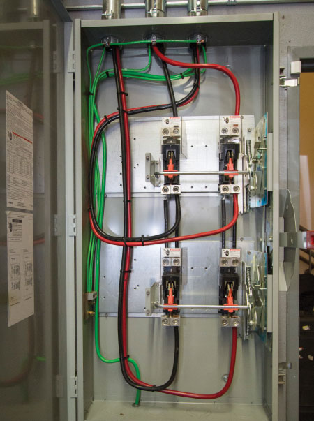
Photo 1. This is a good example of the wire bending space requirements found in Article 312. The conductors that enter from the top and terminate in the highest lugs would be considered as entering the opposite wall as in 312.6(B)(2); all the others would have to meet the requirements of 312.6(B)(1).
Article 312 begins with installation requirements for damp and wet locations. Some basic items here are related to prevention of moisture accumulation within the enclosures and the need for a ¼″ airspace between the enclosure and the mounting surface. Positioning within walls is covered next, and you are allowed a ¼″ setback if in concrete, tile or other non-combustible materials. If you have a combustible finish wall, you must have cabinets flush or projecting past the surface. These are some of the most basic items to look for, but please review your codebook to fill in the other items I have skipped.
One of the most important items (in my opinion) is the Deflection of Conductors requirement in 312.6. This is the portion of the code that gives us the required bending space for conductors, which depends on both the size of the conductor and where it enters the enclosure in relation to the termination position. Naturally, bending the conductor allows us to have a slight reduction in the required space, and it is easier to make a 90 degree bend into a terminal point. Please keep in mind that these are based on the minimum bending radius of conductors, and we should not make sharp right-angled bends.
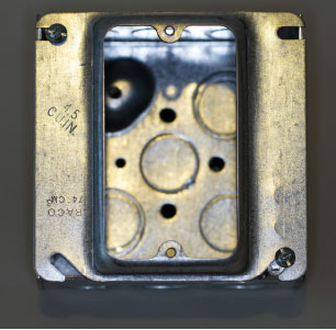
Photo 2. This is a steel box with a trade size of 4 x 2 1/8, so in Table 314.16(A) we find a volume of 30.3 cubic inches. However, the plaster ring has a volume of 4.5 cubic inches (as seen in the photo) for a total of 34.8 cubic inches.
When the conductors enter the wall of the enclosure opposite the termination, then we have to make two offset bends (unless you have the rare occasion where the conductor enters directly across from the termination), thus the need for additional space with these connections. Read the language carefully in order to understand when to apply each table, and familiarize yourself with both Tables 312.6(A) and (B). Table 312.6(A) deals with conductors not entering or leaving the opposite wall, so if we are using a typical wall mount panel and we have the conductors entering the top of the enclosure and the terminations of the branch circuit breakers are horizontal (meaning they are facing 3 o’clock and 9 o’clock), then this table gives us the required bending space. If we use the same example and the conductors enter in the right side of the enclosure they would be opposite the termination, and Table 312.6(B) would be used.
Often we have parallel runs for the same circuit that have to be terminated into the same device. This is where we apply the extra columns of these tables under the headings of “wires per terminal.” This concludes our brief review of some of the requirements in Article 312. In my experience, these are the things that combination inspectors encounter most often.
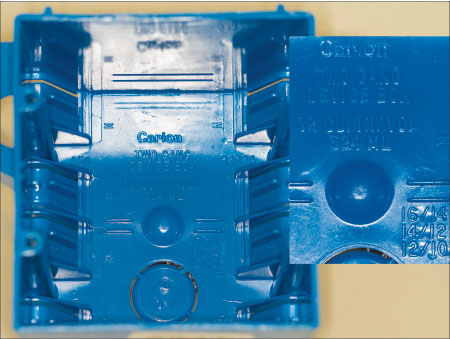
Photo 3. Plastic box volume cannot be found in Table 314.16(A). Therefore, each box is required to be marked with the volume. Also, note that in the lower right corner of the inset photo, the manufacturer helps you by giving the maximum number of conductors allowed if using all the same size. The middle line indicates that fourteen 12 AWG conductors are permissible. Also, note that these cable clamps are considered internal.
Installations that must comply with Article 314 are found more often in the combination world, and yet these rules are frequently misunderstood or not enforced. Please review the beginning of this article on your own, and we will start our coverage with 314.16.
In 314.16, we find the allowable number of conductors in outlet, device and junction boxes, and conduit bodies. First, let’s get conduit bodies out of our way in 314.16(C). First, I have to explain that we have two types of conduit bodies: standard conduit bodies and short-radius conduit bodies, which in the field are commonly referred to as SLBs (see 314.16(C)(3) for details).
Conduit bodies are made with an interior volume that is generally twice the volume of the largest possible conduit entrance. So if the conduit fill requirements are followed, we typically never have a problem with conduit body fill issues. The field issues we usually see with conduit bodies come from splices, taps or devices. In 314.16(C)(2) we find that only where we have volume measurements clearly marked by the manufacturer are we allowed to have splices or taps. If you see splices or taps in a conduit body, please refer to Table 314.16(B) for a volume calculation factor to be used based on the number of conductors. You have to check and see if they have exceeded the volume of the conduit body as labeled.
Enough said on conduit bodies, now let’s get to boxes. Overfilled boxes lead to all kinds of issues. We need enough room within each box for any devices to be used, as well as sufficient space for heat to dissipate without causing damage to the conductors or the devices. Devices today seem to be getting larger and larger. USB outlet combination devices are the latest devices I’ve seen which are larger than the normal receptacle; and, of course, we have dimmers or occupancy sensors which are larger than normal switches.
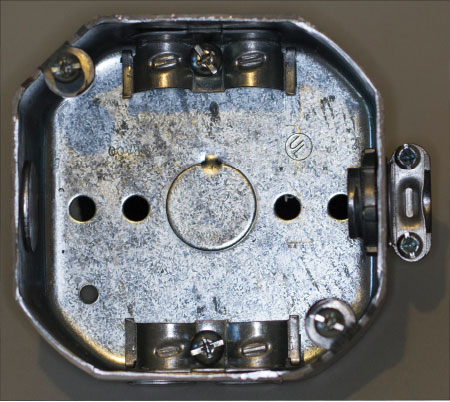
Photo 4. This photo illustrates both internal cable clamps (top and bottom) and an external clamp located on the right side.
With this in mind, we have limits on how many conductors we allow. I have seen electricians who have used the end of hammer handles to force conductors back into a box to create enough room for the devices to be installed; not a good practice, obviously! At times, this type of abuse can lead to damaged insulation of conductors, loosening of terminations within wire nuts, and other dangerous conditions.
If we are dealing with industry standard metal boxes, we should refer to Table 314.16(A) which gives us the standard dimensions and volumes of these boxes. I start here because these boxes are not marked with a volume number. The metal boxes usually also accept what is known as a plaster ring, or at times extension rings. In these cases, as long as the plaster trim ring or extension box has a volume measurement on it, then you would add this to the box volume for the total volume of the assembly.
When we deal with plastic boxes, which are not just simple cubes in their design, the manufacturers are required to mark the volume measurement on the box. These are usually embossed on the plastic box. So how do these volumes relate to conductors and devices? We need to use Table 314.16(B), which gives us a volumetric requirement for conductors size 18 AWG through 6 AWG. Most commonly, we use 14, 12 and 10 AWG, so I would encourage you to memorize those numbers: 14 AWG has a value of 2 cubic inches; 12 AWG jumps to 2.25 cubic inches; and 10 AWG is 2.5 cubic inches. We often have boxes that do not have all the same size conductors, as it is common to have 12 AWG for receptacles and 14 AWG for lighting. So, if you have a switched outlet, there will be both 14 AWG and 12 AWG in the same multi-gang switch box. If the box contains only one size conductor, then it is quite simple to follow the numbers in Table 314.16(A) or the numbers given by the plastic box manufacturer, embossed into the box.
Now that we have some of the basics covered, let’s go back and review 314.16(B), which is broken down into five sections. First, we are told that each conductor that originates outside the box and terminates within the box will get one volume count according to the size of conductor. If you have pass-through conductors that do not terminate to anything within the box, we have to count each of these as one volume count. If you have conductors that pass through the box but also have a large loop of excess wire (double the minimum required for free conductors), then we count those conductors as a double volume count. If you have a pigtail for makeup that does not leave the box, it doesn’t have to be counted.
Now we have to consider the cable clamps. If the box has any cable clamps within the interior of the box, we have to count them as a single volume count of the largest conductor within the box. So if we use one clamp or four clamps, it is still just a single volume count. If we have any lighting support devices, also called studs or hickeys, then again we have to add one volume count based on the largest conductor.
That brings us to devices, receptacles and switches. Each strap or yoke that holds a receptacle or switch, or multiple receptacle or switches, has to have a double volume count based on whatever size conductors are connected to that device. If you are using a larger device (for example a 50-amp receptacle) that is wider than a single (2 inch) device box, then you have to count a double volume allowance for each gang required for mounting such a device.
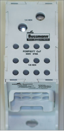
Photo 5. This is an example of a power distribution block. In 314.28(E)(4), the code requires the live parts to be covered. This photo shows a totally insulated unit which is considered finger safe.
The last item to cover in box fill calculations is the room needed for the equipment grounding conductors. The basic rule is that we must take a single volume allowance for all the grounds combined, based on the largest grounding conductor. So if you have two 14 AWG, five 12 AWG and one 10 AWG, then we would take a 2.5 cubic inch volume addition based on the 10 AWG grounding conductor.
Box fill calculations is one of the most basic items for inspectors; yet for years, I have seen inspectors just walk by these violations, either due to their ignorance of the code or they just don’t consider it important. If you’ve ever been an electrician and had to do service work in a box that was overfilled, it would convince you that this code requirement should not be taken lightly. A little trick I would use if I found a box overfilled during inspections would be to take out a writing utensil and just do the calculation on the face of the stud. For example: five 12 AWG = 11.25; 2 devices = 9; 12 AWG ground = 2.25; then I would total it 22.5. I would then write the violation on my ticket, such as “overfilled box, end of hallway switch, see calculation on stud.” To this day, contractors remember this practice and have mentioned it to me.
The next item for combination inspectors would be 314.20, which deals with the box mounting details. If you have boxes in non-combustible surfaces such as concrete, tile, gypsum, or plaster, the box must be installed so that the front edge of the box is no more than ¼ inch back of the surface. This can be quite a challenge, and is often not enforced nearly as well as it should be. If you are dealing with combustible surfaces, like wood, then the boxes have to be totally flush or project past the surface. As I said, it is a challenge to get the ¼ inch, so perfectly flush is even more of a task. The concept here is that if for some reason we have an arcing event inside a box, we absolutely do not want to ignite anything outside the box. If we maintain this code requirement, we minimize the possibilities of a dangerous condition while we are waiting for the overcurrent devices to operate. In 314.21, the code addresses repairing noncombustible surfaces where we have a gap or open space larger than ⅛ inch at the edge of the box.
Please review 314.23, Supports, on your own. One piece of advice I would offer when inspecting for these items is to take a closer look if the mounting of a box does not look like a nice clean installation. I have seen people violate the UL listing of many boxes by just drilling holes into the interior sides of the boxes, and installing nails or screws to mount them in ways that are not tested and approved. There always seems to be an inventive installer who just doesn’t have exactly the right box for the application, so in an effort to “get the job done” the installer creates code enforcement headaches which then result in contractor headaches.
Section 314.24, Depth of Boxes, seems like it would be a basic requirement. However, as I mentioned before, in today’s environment of ever more sophisticated control devices that are getting larger in size, we must allow for increased depth. Part of 314.24(B)(1) addresses this: where the devices are deeper than 1-⅞″, then the box to mount these in must have a depth at least ¼″ deeper than the device. Also in (B)(3), (4) and (5), you will find minimum depths for boxes in relation to the conductors being used.
Section 314.27, Outlet Boxes, starts with (A), which covers boxes used for mounting luminaires. Let’s think about this for a while. We are typically not concerned about the support capabilities of boxes that are used just for devices, such as switches and receptacles. However, when it comes to luminaires that at times can weigh several hundred pounds, we must give the support capability some consideration. If we have a wall-mounted box, it must be listed for the weight permitted to be supported by the box alone, if it is other than 50 pounds. A similar requirement applies to ceiling light boxes. If the luminaire weighs more than 50 pounds, then that luminaire shall be independently supported by some means other than the box alone, unless the box is listed and marked to support at least the actual weight of the luminaire.
Floor boxes must be listed specifically for the use when installing receptacles in the floor. I have seen attempts to use normal wall boxes as floor boxes a few times; however, the use of devices and boxes in the floor are subject to more abuse and special conditions that must be considered during the design and listing stages. Make sure these are properly listed as floor boxes and are installed in accordance with the manufacturer’s instructions.
Ceiling-Suspended (Paddle) Fan Outlet boxes must also meet some special requirements. Some of the unique concerns here (besides weight) are the vibration and oscillation of the fan. Therefore, boxes need to be listed and labeled for the purpose. Please review 314.27(C) for the exact details related to the weight limits and marking requirements for ceiling fan boxes.
The last part of Article 314 we are going to cover is 314.28, Pull and Junction Boxes and Conduit Bodies. First, the language tells us that the minimum size requirements only apply to installations where the raceways entering the junction box or conduit body contain conductors 4 AWG or larger. So how do we size these boxes? In (A)(1), (2), and (3) we find the rules for sizing. If you have a straight pull, meaning the conduit(s) enter one wall and exit the opposite wall, then we use (A)(1). This gives us a simple method to size the box: it must have a dimension from one side to the other that is 8 times the size of the largest raceway coming into the box. So if it is a 3 inch conduit, then the minimum length for the box would be 24 inches. These are often used as pulling points in long conduit runs and you must have some working distance within these boxes for pulling and feeding these larger conductors.
Where we have angle or U pulls or splices within a pull or junction box, the size varies for the above. Here we take the size of the largest conduit and multiply it by six, and then add the sum of the rest of the conduits in the same row in the same wall; this will give you the minimum distance to the opposite wall of the junction box. If you have multiple rows then you calculate each row and use the largest number. So if you have a 4-inch, two 2-inch and five 1-inch conduits, you would take 6 times 4 = 24 plus 9 for a total minimum distance of 33 inches, which you can’t normally find, so you would settle on a 36-inch junction box.
In 314.28(E), the code covers power distribution blocks installed within these boxes. First, the power distribution block must be listed. Second, if it has a minimum box size required in the installation requirements that exceeds the size required by the code, you must use the larger size. The last two items to be aware of for power distribution blocks include proper wire bending space for the terminations as required by 312.6 and that uninsulated parts must not be exposed, so they must have some type of covering or be finger safe.
This article only hit the high points in Articles 312 and 314, so don’t forget to read both articles in their entirety so you have some familiarity with what is in the Code. In the next article, we will begin discussing the wiring methods in Chapter 3.