Through the exceptional efforts of the members of NFPA NEC Code-Making Panel 4 working with the proposals and comments that were submitted for the 2014 Code, significant changes have been made to Section 705.12(D), Load Side Connections for Utility-interactive PV Inverters. These changes will allow better understanding of the requirements for load-side connections of utility interactive inverters and will clarify requirements that were not fully described in previous editions of the code. Not only will AHJs and plan reviewers benefit from these changes, the PV installer will also have significantly improved guidance in this area.
All material in quotations below is taken from the 2014National Electrical Code (NEC), ANSI/NFPA 70. Bold italics text represents changes from the 2011 NEC.
Introductory Paragraph 705.12(D)
“705.12(D) Utility-Interactive Inverters. The output of a utility interactive inverter shall be permitted to be connected to the load side of the service disconnecting means of the other source(s) at any distribution equipment on the premises. Where distribution equipment, including switchgear, switchboards, or panelboards, is fed simultaneously by a primary source(s) of electricity and one or more utility-interactive inverters, and where this distribution equipment is capable of supplying multiple branch circuits or feeders, or both, the interconnecting provisions for the utility-interactive inverter(s) shall comply with 705.12(D)(1) through (D)(6).”
The word “switchgear” has been added to the list of distribution equipment. And as in past editions of the Code, distribution equipment is not specifically defined. Of course, we all know what it means and numerous examples are usually given. But, we must also consider that distribution equipment in the form of junction boxes for taps or new panelboards can be added to the premises wiring at almost any location that is allowed by the Code. So essentially, connections for utility-interactive inverters can be made at many points on the load side circuits that are not in existing distribution equipment.
705.12(D)(1) Dedicated Overcurrent and Disconnect
“The source interconnection of one or more inverters installed in one systemshall be made at a dedicated circuit breaker or fusible disconnecting means.”
This section has been revised to specifically require that multiple inverters in a single PV system shall be connected to the existing premises wiring system at a single dedicated circuit breaker or fusible disconnecting means. This section no longer allows multiple connections to a load center or panelboard where there are multiple inverters involved. Multiple inverters must first be combined in an AC combining panel and the output of that panelboard is then connected to the single point of connection in the distribution equipment through one circuit breaker or fusible disconnecting means. See diagram 1.

Diagram 1. 705.12(D)(1) Single PV connection allowed.
Unfortunately, we do not have a definition of “PV system” in the Code. This will be a gray area that must be interpreted by the AHJ. What happens when there are ten widely distributed PV “systems” on a large structure such as a mall? What happens if each “system” must be individually metered and connected to separate load centers for net power flow to separate facilities? Is this one system or can each system be considered separately? What about a large residence, with an inverter and modules on the garage and another set of modules and inverter on the main house? What about the situation where one inverter is fed by an array on the east facing roof and a second inverter is fed by an array on the west facing roof and the inverters are not co-located? And then there is the apartment building or condo where one structure may have three of more separate systems, each requiring a separate connection to individual load centers for net power purposes. Are all of these examples of one system? Or are they multiple systems that might be connected to the premises wiring at multiple points? Again, the AHJs will have to make the call.
It would appear that where multiple inverters are co-located in a single structure or facility and there is only one “user/owner/customer” of those multiple systems, they must have their outputs combined before a connection is made to the existing premises wiring system. And, as PV modules get more efficient and costs come down, we may see increasing numbers of multiple inverter systems on single buildings.
705.12(D)(2) Bus or Conductor Ampere Rating
“One hundred twenty-five percent of the inverter output circuit current shall be used in ampacity calculations for the following:”
Note that the title of the section remains bus or conductor ratings and will apply to both as they are defined in the introductory paragraph. The first noteworthy change in this section is the use of a factor of 125% of the inverter rated output current in calculations for busbar ratings and conductor ampacity. In the previous code, the rating of the overcurrent device protecting the inverter output circuit was used in the calculations. This new allowance may slightly reduce the required busbar and conductor ratings required by the following calculations.
Feeders
Feeder Ampacity
“(1) Feeders. Where the inverter output connection is made to a feeder at a location other than the opposite end of the feeder from the primary source overcurrent device, that portion of the feeder on the load side of the inverter output connection shall be protected by one of the following:
(a) The feeder ampacity shall be not less than the sum of the primary source overcurrent device and 125 percent of the inverter output circuit current.
(b) An overcurrent device on the load side of the inverter connection shall be rated not greater than the ampacity of the feeder.”
This section represents a significant change from past code requirements. It presents requirements for feeder size and overcurrent protection when the utility interactive inverter connection is notat the opposite end of the feeder from the utility connection.
PV Opposite Utility On the Feeder (Not addressed by Code)
Since, the situation where the PV connection is at the opposite end of the feeder is not addressed in the new requirements, we can assume (sometimes not a good thing to do) that there is no ampacity correction required on the feeder under that situation. The size of the existing feeder was determined by the existing overcurrent device protecting that circuit from utility currents. Consider the feeder carrying PV currents with fused disconnects in the feeder at various points.
Additionally, while locating the PV inverter output connection at the opposite end of the feeder from the utility source will prevent the feeder from being overloaded by additive currents, it is obvious that 125% of the rated inverter output current must not exceed either the rating of the utility-end overcurrent device or the ampacity of the existing feeder.
Existing Load Taps of the Feeder (Not addressed by Code)
However, if that existing feeder has been tapped for load(s), common sense would dictate a close look at the tap rules because now there are two sources of current that can feed the tap conductor, and the tap rules and tap conductor size used initially may no longer be appropriate.
In (a), a PV connection is made to the feeder somewhere along the feeder, but not at the end opposite the utility connection. The portion of the feeder, from the connection point to the load end of the feeder can be subjected to currents that are additive and can be as high as the rating of the existing utility end overcurrent device protecting the feeder plus the output of the PV inverter. Hence, the conductor from the connection point to the load end of the feeder must have an increased ampacity equal to the sum of the existing overcurrent device protecting the feeder and 125% of the inverter output rating as noted in this section. See diagram 2.

Diagram 2. 705.12(D)(2)(1)(a) Increased feeder ampacity required.
In (b), an allowance is made to protect the existing feeder by installing an overcurrent device on the feeder on the load side of the connection point at the connection point. This allowance, with the added overcurrent protection rated the same as the existing feeder, will allow the existing feeder to be retained and not be replaced as may be required in (a). The addition of this overcurrent device will prevent excess load currents or faults from exceeding the ampacity of the feeder. See diagram 3.

Diagram 3. 705.12(D)(2)(1)(b) Additional breaker required.
Inverter Output Circuit (the tap conductor) Size
“(2) Taps. In systems where inverter output connections are made at feeders, any taps shall be sized based on the sum of 125 percent of the inverter(s) output circuit current and the rating of the overcurrent device protecting the feeder conductors as calculated in 240.21(B).”
Significant engineering analysis by code-making panel members and others went into this change concerning the use of the tap rules in section 240.21(B). While an overcurrent device and a disconnect are still required at the output of each utility-interactive inverter, that overcurrent protective device does not have to be at the tap point on the feeder. The tap rules allow the overcurrent device to be on the tap conductor at various distances from the connection point to the feeder. The inverter output overcurrent protective device is still required to be 125% of the inverter output rating; and, of course, there may be rating round up involved in selecting an appropriate overcurrent device. However, when calculating the required ampacity of the tap conductor under the various tap rules, the actual factor of 125% of the inverter rated output current is used and not the overcurrent device rating. Again, this may yield slightly reduced conductor sizes. See diagram 4.

Diagram 4. 705.12(D)(2)(2) Tap rules used to locate PV breaker and determine conductor ampacity
Busbars
“(3) Busbars. One of the methods that follows shall be used to determine the ratings of busbars in panelboards.
Busbar Rule (a)
(a) The sum of 125 percent of the inverter(s) output circuit current and the rating of the overcurrent device protecting the busbar shall not exceed the ampacity of the busbar.
Informational Note: This general rule assumes no limitation in the number of the loads or sources applied to busbars or their locations.”
This worst-case requirement presented in (a) assumes that the utility current through the existing main breaker and the current from the output of the utility-interactive inverter may add and that current may create an overload on the busbar. There are no restrictions on the location of the main utility breaker or the PV backfed breaker. If the busbar has a rating equal to the sum of these two values, then no overload would be possible.
It should be noted that reductions in the size of the utility breaker are not prohibited in this section and could be accomplished if allowed by other sections of the Code, load calculations and equipment limitations.
Busbar Rule (b)
“(b) Where two sources, one a utility and the other an inverter, are located at opposite ends of a busbar that contains loads, the sum of 125 percent of the inverter(s) output circuit current and the rating of the overcurrent device protecting the busbar shall not exceed 120 percent of the ampacity of the busbar. The busbar shall be sized for the loads connected in accordance with Article 220. A permanent warning label shall be applied to the distribution equipment adjacent to the back-fed breaker from the inverter that displays the following or equivalent wording:
WARNING:
INVERTER OUTPUT CONNECTION;
DO NOT RELOCATE THIS OVERCURRENT DEVICE.
The warning sign(s) or label(s) shall comply with 110.21(B).”
Section (b) is similar to the requirement found in previous editions of the code. If the two sources (utility and PV) are at opposite ends of the busbar, then the sum of those two sources can be as high as 120% of the busbar rating. With this location of sources, it is not possible to overload the busbar. Note that the busbar must be sized for the loads that are connected. The reason for the value of 120% is lost in history, but may be related to potential thermal overloading of the panelboard. The warning label is self-explanatory and the new requirement referring to section 110.21(B) gives additional information on the specifics of the appearance and durability of the warning label.
Busbar Rule (c)
“(c) The sum of the ampere ratings of all overcurrent devices on panelboards, both load and supply devices, excluding the rating of the overcurrent device protecting the busbar, shall not exceed the ampacity of the busbar. The rating of the overcurrent device protecting the busbar shall not exceed the rating of the busbar. Permanent warning labels shall be applied to distribution equipment that displays the following or equivalent wording:
WARNING:
THIS EQUIPMENT FED BY MULTIPLE SOURCES.
TOTAL RATING OF ALL OVERCURRENT
DEVICES, EXCLUDING MAIN SUPPLY
OVERCURRENT DEVICE, SHALL NOT EXCEED AMPACITY OF BUSBAR.
The warning sign(s) or label(s) shall comply with 110.21(B).”
Section (c) provides an alternate method of sizing the PV backfed breaker, or determining the size of the required busbar if the PV backfed breaker rating is known. This section will most likely be used when connecting PV to a subpanel or when sizing inverter ac combining panelboards. After excluding the main breaker from the utility, the sum of all remaining breakers, both load breakers and the PV supply breaker may not exceed the rating of the busbar. There are several aspects to this requirement that need close inspection and consideration.
First, the main breaker before the addition of any PV has been sized to protect the busbar from possible overload from utility currents. The main breaker will always be equal to or smaller than the busbar rating. For example, many load centers have a 125-amp busbar, but only a 100-amp main breaker. In a normal panelboard or load center, the ratings of the load breakers will total more than the rating of the main breaker or the busbar in nearly all circumstances. If this situation exists, then no PV can be added because the requirement cannot be met because the sum of the load breakers already exceeds the rating of the busbar. However, if the sum of the load breakers were equal to the rating of the busbar, that busbar would still be protected both by the main breaker and by the fact that excess current over the busbar could not be drawn through the load breakers. And again, under this condition, no PV backfed breaker could be added. However, as the sum of the load breakers is reduced, there becomes an allowance for adding a backfed PV breaker with increasing ratings. In the extreme case, there could be a situation where there are no load breakers and only a single backfed PV breaker rated the same as the busbar. In any of these cases, no matter where the PV breaker is installed on the busbar, the supply and/or load currents cannot exceed the rating of the busbar.
But, it should be noted that in existing load centers, with the sum of the load breakers totaling more than the busbar rating, it is unlikely that load and load breakers can or will be removed.
And, of course, it would not be wise to install a backfed PV breaker that was larger than the main breaker in those instances where the busbar rating is larger than the main breaker. If this were done, the main breaker could trip from over currents through the larger PV breaker.

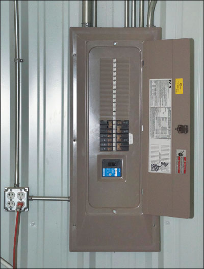
Photo 1. Panelboards and load-side connections — many changes for plan reviewers and inspectors in 2014.
But, this section needs to be used with extreme caution because there is no restriction on the position of the backfed PV breaker. Suppose a 50-amp PV breaker were installed near the top of the 100-amp busbar in the load center near a 100-amp main breaker and there were 50 amps of load breakers. The code requirement is met with this configuration. However, what happens if someone disregards the warning label or the label simply falls off over time? I suspect that many jurisdictions are going to have to emphasize the permanent nature of that warning label to cover the materials that it is made of and the manner in which it is fixed to the panel board. Also, some consideration might be made to permanently covering unused panelboard breaker positions. It might be wise to adopt a local jurisdiction requirement that the backfed PV breaker always be installed as far as possible from the main utility breaker and an additional warning label as required in (b) be placed adjacent to this PV breaker, or other PV overcurrent device.
Center-fed Panelboards
“(d) Connections shall be permitted on multiple-ampacity busbars or center-fed panelboards where designed under engineering supervision that includes fault studies and busbar load calculations.”
There was no provision in earlier codes to address center-fed panel boards and it was not possible to install the PV breaker at the opposite end of the busbar from the main breaker because there were two busbars connected to the main breaker. Section (d) was specifically added to the 2014 Code to address the common situation where PV needs to be connected to a center-fed panelboard. Although not clearly stated, there was no intent to allow center-fed panelboards to be installed under sections (a) through (c) of 705.12(D)(3). PV connections are now allowed on center-fed panelboards under the conditions noted in this section. Engineering supervision typically indicates that the analysis of the center-fed panel board connection will be made and stamped by a professional engineer. The load calculations will look not only at the breakers installed on the busbars, but also the loads connected to those breakers, and the possibility of installing additional breakers and loads in unused spaces in the panelboard. Fault studies may involve looking at the electrical time versus current profiles for each of the circuit breakers involved to ensure that all portions of the busbars will be protected under various fault scenarios from currents sourced both from the utility through the main breaker and from the PV system through the backfed PV breaker.
Marking (3), Suitable for Backfeed (4), and Fastening (5)
These sections are unchanged from the 2011 NEC.
Wire Harness and Exposed Cable Arc-Fault Protection
“(6) A utility-interactive inverter(s) that has a wire harness or cable output circuit rated 240 V, 30 amperes, or less, that is not installed within an enclosed raceway, shall be provided with listed ac AFCI protection.”
This requirement will apply mainly to microinverter systems that have inverter ac output cables and trunk cables that are not installed in conduit.
Summary
It is obvious that the new 705.12(D) requirements are significantly different from those in past years. While many of them make sense from an engineering point of view, the real world faced by inspectors and plan reviewers may be somewhat different where people typically ignore instructions, ignore the Code, and ignore warning labels. On the other hand, PV systems have not changed significantly from 2011 to 2014 and the electrical systems they are being connected to have not changed significantly, so these new requirements might also be applied in jurisdictions using earlier editions of the Code by accepting alternate methods and materials waivers based on the 2014 NEC clarifications.