The current Canadian Electrical Code Part I (CE Code) has special terminology for a high voltage station that states, “Station – an assemblage of equipment at one place, including any necessary housing, for the conversion or transformation of electrical energy and for connection between two or more circuits.” This special terminology has remained unchanged since introduction in the fourteenth edition of the CE Code, dated 1982. Prior to 1982, high voltage stations were referred to as high potential installations. In the first edition, dated 1927, high potential installations were limited to between 601 V and 5000 V. The fourth edition, dated 1939, changed high potential installation to those above 750 V with clearance tables up to 15 kV. The next edition, dated 1947, added two clearance tables covering installations up to 69 kV. Additional clearances for installations up to 115 kV were added in the seventh edition, dated 1958. In the fifteenth edition, dated 1986, a reference to CSA Standard C22.3 No. 1 Overhead systems, expanded high voltage installation to include all high voltages. The rest of this article will focus on outdoor stations up to 35kV.
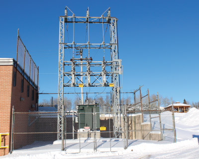
Photo 1. A typical H-frame station
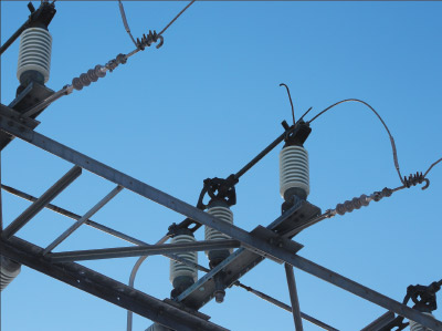
Photo 2. A typical horn gap switch (airbreak switch)
The next step in the evolution was to modify the enclosures for the fused switch and the transformer to make it tamper-resistant. Tamper resistance requirements can be found in CSA transformer standard C227.4 Three-phase, Pad-mounted Distribution Transformers with Separable Insulated High-voltage Connectors. C227.4 defines tamper-resistant as the state in which the completely assembled apparatus resists unauthorized entry when tested in accordance with ANSI C57.12.28. To be tamper-resistant the enclosure could not have any exposed bolts, and each hinged door secured by Penta bolts with a sleeve to and the metal door over the viewing window also secured by a Penta bolt.

Photo 3. An interlock for the airbreak switch
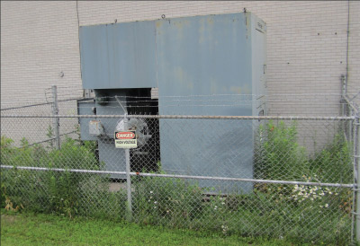
Photo 4. This station has an enclosed fused switch and conductor to the transformer originally installed in 1973. Note the lack of maintenance of the ground surface covering layer.
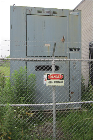
Photo 5. The load-break switch enclosure. Note the viewing window that allows the switch knife blades to be visible in the open position as required by CE Code Rule 36-214

Photo 6. A typical Penta bolt with a sleeve
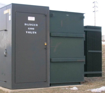
Photo 7. A sample of a tamper-resistant unit substation known as a TLO, originally installed in 1990.
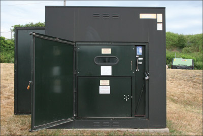
Photo 8. The front door is open on a TLO showing the switch and fuse compartments. Note the viewing window that allows the switch knife blades to be visible in the open position as required by CE Code Rule 36-214.
Advantages of having tamper-resistant enclosures forming a station are profound, as the station is safer to the general public, easier to maintain, more compact, no station fence is required, and less grounding is required. The station is safer to the public as the ungrounded conductor is no longer exposed and is less likely to have children or unauthorized persons touching the ungrounded conductor. The station is easier to maintain as the personnel doing the maintenance of the ground-surface covering layer referred to in CE Code Rule 36-204(5) are not exposed to the hazards typically found within the station fencing. The station is more compact, saving money and real estate. Finally, the station fence including the fence grounding is not needed; this saves on installation costs, resulting in an installation that will be less attractive to copper theft.
The first manufacturer to offer a tamper-resistant station was Markham Electric (no longer in business) and the station was known as a TLO (transformer, low profile, outdoor). These tamper-resistant stations consisted of a load-break switch, high-voltage fuses, lightning arresters, oils filled distribution transformer and a secondary termination compartment.
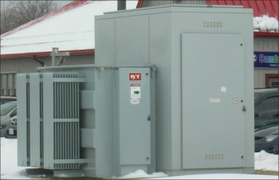
Photo 9. Tamper-resistant S&C switchgear close-coupled to a Pioneer Transformer tamper-resistant transformer
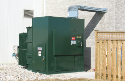
Photo 10. A unitized pad-mounted transformer manufactured by Pioneer Transformers Ltd.
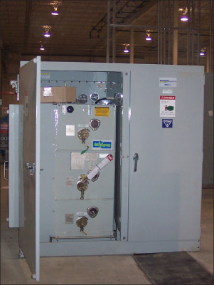
Photo 11. A unit station with a SF6 switch and transformer called a Minisub; manufactured by Power Systems Technology.
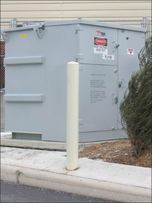
Photo 12. A unit with a transformer and an oil-filled switch known as a VisiTran; manufactured by Carte International Inc.
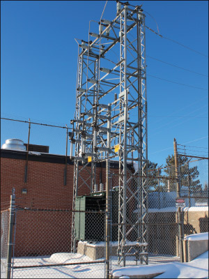
Photo 13. Typical design of an H-frame station with open live conductors and a station fence
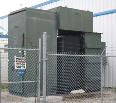
Photo 14. A metal enclosed station with no exposed conductors and a station fence
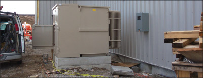
Photo 15. A tamper-resistant station with no exposed conductors and no need for a station fence
Other examples of tamper-resistant stations now include tamper-resistant switchgear close-coupled to a tamper-resistant transformer, contained unit stations including a load-break switch and transformer in one enclosure known as a unitized pad-mounted transformer, a unit station with a SF6 (sulfur hexafluoride) switch and transformer, and a unit with a transformer and an oil-filled switch. All of these examples provide tamper-resistant design including switches with visible isolation and interlocking to the fuse compartment door.
As can be seen, stations have evolved considerably over the last 50 years. The evolution has produced a station that is more compact, safer, easier to maintain, and less attractive to copper thieves.


Find Us on Socials