The 2014 National Electrical Code contains numerous changes that affect wire and cable installations. This article will cover a few of the highlights, discuss why the changes were made, and explain what they mean for code users.
Carry me over the threshold
One of the first changes is a code-wide change from the standard 600-volt threshold to 1000 volts. A change of this type hasn’t occurred since the 1920 NEC, when the threshold was raised from 550 volts to 600 volts. This change recognizes the growing need for recognition of voltage systems between 600 and 2000 volts, particularly in renewable energy systems. As a first step for wire and cable, a note was added to Table 310.104(A) indicating that “Conductors can be rated up to 1000 V if listed and marked.”
Pretty in … gray?
A new option was added to 200.6 to allow three gray stripes for identifying the grounded (neutral) conductor. Previously, the code allowed solid white, solid gray, or three white stripes. The new allowance for three gray stripes is particularly useful for complying with 200.6(D), which requires installers to identify grounded conductors of different systems installed in the same raceway, cable, box, auxiliary gutter, or other type of enclosure.
I’m good enough, I’m smart enough, and doggone it, people like me!
Photovoltaic (PV) wire has become more robust and versatile over the last few years. In the 2014 NEC, language was added in 690.81 stating that “PV wire that is listed for direct burial at voltages above 600 volts, but not exceeding 2000 volts, shall be installed in accordance with Table 300.50, Column 1.” Additional changes were made in 300.50(A)(2) for directly buried conductors with insulation types up to 2000 volts: “In industrial establishments … nonshielded single-conductor cables with insulation types up to 2000 volts that are listed for direct burial shall be permitted to be directly buried.” In the U.S., the only nonshielded single conductor listed for both 2000 volts and direct burial is PV wire. This type of wire is often used from the combiner to the inverter in large-scale ground-mount photovoltaic installations that are not accessible to the public.
PV wire is listed under Outline of Investigation UL 4703. UL 4703 is currently undergoing evaluation in UL Standards Technical Panel (STP) 4703, and will become a full standard when all required steps are completed. The added code language means that 2000 volt PV wire that is listed for direct burial is now explicitly recognized by the code and requires no additional physical protection other than the minimum cover requirements in Table 300.50.
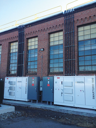
Photo 1. Vertical jacketed MC Cable installation
The only constant is change
Once again, Code-making Panel 6 hotly debated the issue of services and feeders for dwellings, and this code cycle brings a major re-write of 310.15(B)(7). For most residential services, the service conductors and main power feeders are allowed to be sized based on the requirements of 310.15(B)(7), which permits a smaller size conductor to be used in many cases. This allowance has been in the NEC since the 1950s in recognition of the fact that only a small portion of the electrical loads in homes are typically used at the same time, so the load on the service conductors at any one time is generally much smaller than the total calculated load.
The language and table in the 2011 NEC were deleted and replaced with the following language:
For one-family dwellings and the individual dwelling units of two-family and multifamily dwellings, service and feeder conductors supplied by a single-phase, 120/240-volt system shall be permitted be sized in accordance with 310.15(B)(7)(1) through (4).
(1) For a service rated 100 through 400 A, the service conductors supplying the entire load associated with a one-family dwelling, or the service conductors supplying the entire load associated with an individual dwelling unit in a two-family or multifamily dwelling, shall be permitted to have an ampacity not less than 83 percent of the service rating.
(2) For a feeder rated 100 through 400 A, the feeder conductors supplying the entire load associated with a one-family dwelling, or the feeder conductors supplying the entire load associated with an individual dwelling unit in a two-family or multifamily dwelling, shall be permitted to have an ampacity not less than 83 percent of the feeder rating.
(3) In no case shall a feeder for an individual dwelling unit be required to have an ampacity greater than that specified in 310.15(B)(7)(1) or (2).
(4) Grounded conductors shall be permitted to be sized smaller than the ungrounded conductors, provided that the requirements of 220.61 and 230.42 for service conductors or the requirements of 215.2 and 220.61 for feeder conductors are met.
Informational Note No. 1: The conductor ampacity may require other correction or adjustment factors applicable to the conductor installation.
Informational Note No. 2: See example D7 in Annex D.
In effect, the same size conductors that are allowed in the 2011 NEC will still be allowed in the 2014 NEC, assuming that temperature correction factors or adjustment factors are not required for the installation. The changes to the code language were necessary to take into account certain limitations inherent in the language in previous code cycles.
It should be noted that the conductor sizing will still be based on the service or feeder rating, not the calculated load. For example, if you have a calculated load of 184 amps and are required to install a 200-amp service, the conductors would be required to have an ampacity of 166 amps or more: 200 amps times 83 percent equals 166 amps. So, for a 200-amp service, you would still be allowed to choose a 4/0 AWG aluminum or 2/0 AWG copper, but you would choose it from the 75 degree C column in Table 310.15(B)(16).
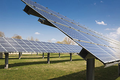
Photo 2. Ground mount PV system using direct buried 2 kV PV wire
Can you take the heat?
XHHW-2 can take the heat! A new exception was added to 310.15(B)(3)(c) Raceways and Cables Exposed to Sunlight on Rooftops. This new exception allows the use of XHHW-2 to be used without applying the ambient temperature adjustments in Table 310.15(B)(3)(c). XHHW-2 was subjected to laboratory tests that proved it would not suffer degradation when exposed to the temperatures generated inside a conduit or cable exposed to sunlight on a rooftop. This allows XHHW-2 to be used in either cables or raceways on rooftops without increasing the conductor size due to direct sunlight exposure.
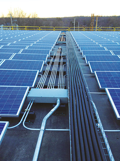
Photo 3. Jacketed MC Cable with XHHW-2 conductors installed on a rooftop
Boats and Cows
Code changes to allow aluminum equipment grounding conductors (EGCs) have been made for agricultural buildings, marinas and boatyards. In 547.5(F) and 555.15(B), the language that restricted EGCs to copper only was changed to also allow aluminum. Substantiation was submitted to the code panel proving that aluminum is at least as safe as copper in these applications. Aluminum ungrounded and grounded conductors were already allowed and frequently used in these locations, and have proven to be safe and reliable.
Hold me tight — but not that tight!
Article 330 contains the installation requirements for Type MC Cable, and a change was made to the requirements for securing in 330.30(B). A new sentence was added stating that “In vertical installations, listed cables with ungrounded conductors 250 kcmil and larger shall be permitted to be secured at intervals not exceeding 3 m (10 ft).” This provides a relaxed requirement from the 6-foot securement requirement normally in effect for MC cable, which means fewer clamps in vertical runs. There are a couple of things to note in this new language: 1) the phase conductors must be 250 kcmil or larger, and 2) the cable must be listed. There is no special listing or testing requirement for vertical runs, but the cable must be listed to UL 1569, and most commercially available MC cables are already listed to UL 1569.
May I see your ID?
New requirements in 210.5(C)(2) and 215.12(C)(2) have been added for identification of branch circuits and feeders supplied from direct-current (dc) systems. With the growth in dc power generation, the number of branch circuits and feeders fed directly from dc systems has also increased; therefore, consistent identification of dc circuit conductors has become more important. With the new requirements, positive polarity is indicated by the color red, a plus sign, or the words “POSITIVE” or “POS.” Negative polarity is indicated by the color black, a minus sign, or the words “NEGATIVE” or “NEG”. A red or black continuous stripe may be used rather than a fully colored insulation. However, a red stripe (for positive polarity identification) may not be applied to a white, gray, green or black conductor; a black stripe (for negative polarity identification) may not be applied to a white, gray, green or red conductor.
The NEC is revised every three years, and these are just a few of the changes contained in the 2014 National Electrical Code. Many jurisdictions have already adopted the 2014 NEC, so check with your local authority having jurisdiction to find out which version of the NEC applies in your locale. Be sure to ask if there are any local amendments that modify the base code. Now that we’ve discussed the current code, it is time to think about the future! The public input process for the 2017 NEC is open for submissions. Go to NFPA.org to submit proposed changes prior to the November 7, 2014 deadline.


Find Us on Socials