Article 310, Conductors for General Wiring, was extensively reorganized for the 2020 National Electrical Code (NEC). In the past, the article had information about ampacity and conductor types all the way from zero to 35,000 volts. Starting with the 2020 cycle, all the requirements for conductors from zero to 2,000 volts are included in Article 310, and the requirements and ampacity tables for conductors over 2000 volts have been incorporated into a new Article 311.
There is a lot of information to cover with the changes within Article 310. In this article, we’ll cover the marking requirements in Section 310.8 and give some examples of cable and conductor markings. In addition, we will look at how other sections and external standards impact how these devices are required to be marked.
Basic Marking Requirements
Section 310.8 contains the basic marking requirements for conductors and cables. It notes that all conductors and cables shall be marked by the manufacturer to indicate five different things. Here is what installers and inspectors are going to be looking for:
- The maximum rated voltage.
- The letter or letters used for identification of the wire. An example would be THWN. That’s really important because it tell us how we can use it and where we can use it.
- The manufacturer’s name, trademark, or other distinctive marking—some way to identify the organization that made that conductor.
- The AWG size or circular mil area.
- Marking on cable assemblies where the neutral conductor is smaller than the ungrounded conductors.
Inspectors, UL, and other industry participants use that information if they have a question about an installed wire or cable or if there’s an issue that comes up during the installation. We are required to have either the AWG size or circular mil area since we have to know how large the cable is to figure out our ampacity. If we have a cable assembly where the neutral conductor is smaller than the ungrounded conductors, this information needs to be marked on the cable. You’ll see that quite often with service entrance cable. It may either have a grounded conductor that is equal to the ungrounded conductors, or it could be smaller. Both versions are available in the marketplace.
Now, I did want to point you to one other resource. We’re looking at the Code and of course, that’s what we’re really discussing today, but there are other resources out there. One of those is the UL Wire and Cable Marking Guide. If you do a simple search for UL Wire and Cable Marking Guide, you can get the PDF as a download. One of the nice things about it is that it gives you a lot of information that isn’t available in the NEC. It tells you about optional marking and what the different letter designations on cables and conductors can mean.
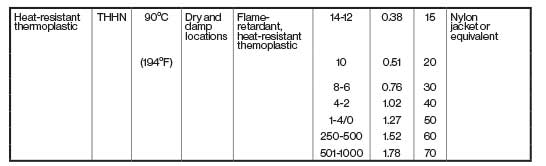
So, for example, look at Table 1 in in the document, UL has it separated by thermoset and thermoplastic insulation, and it tells us what the corresponding NEC article is, what the category code is that UL uses for that particular type of wire or cable, temperature rating (for both dry and wet locations), the permissible voltages, and so forth (see figure 1). There’s a lot of good information and one of the things that you’ll notice when you look at a conductor print legend (the surface marking on a conductor) is that there are a lot of acronyms, a lot of initialisms, and a lot of letters. They all have a meaning.
Stranding Methodologies
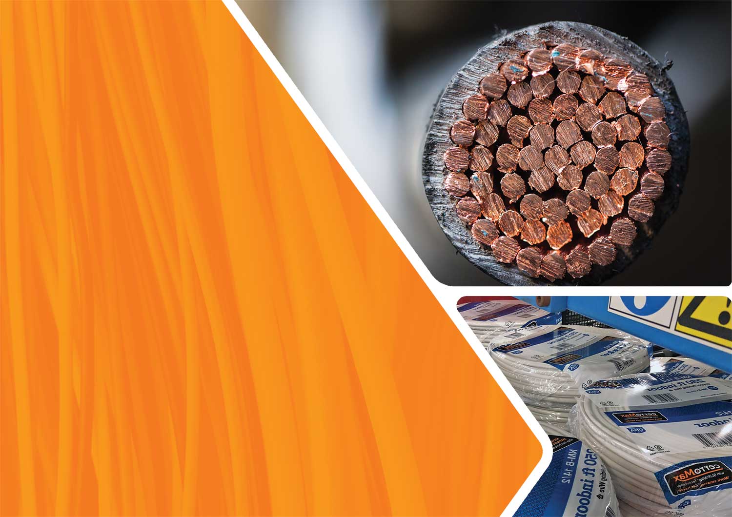
You will also see when you look at different conductors that we have different stranding methodologies. Two basic divisions are solid conductors or stranded conductors. But when we look at stranded conductors, they can take all kinds of different forms (see figure 2).
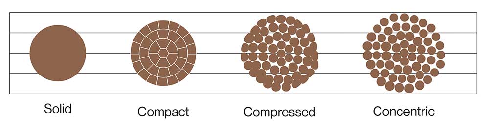
If they simply have individual strands grouped together, then we have a concentric stranding. This is used a lot in utility wire and has the most space between the individual strands.
If you look at, for example, 600-volt copper building wire, most of that is compressed. What happens is that the manufacturer takes all of those strands, they twist them together and then they apply some compression using a die during the process to reduce the outer diameter by a small amount. It’s usually about 3% smaller than a concentric conductor.
If additional dies are used, the result is compact stranded conductors that are used for 600-volt aluminum building wire. They could also be used for medium voltage copper or aluminum conductors. What you’ll see is that there is very little if any air between the strands. These spaces are called interstices and are present between each of these individual strands. So, the smaller those are, the smaller the outer diameter of the conductor is.
It’s important to realize that it doesn’t matter which of these stranding methodologies you use. The ampacity is based on the AWG or circular mil size, so it doesn’t make a difference if it’s solid, compact, compressed, or concentric when you’re calculating ampacity.
Cable Marking Example
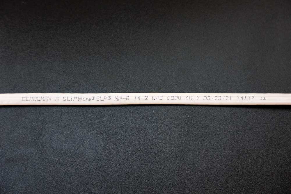
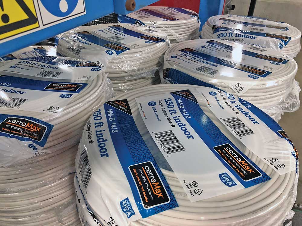
Photo 1 is an example of the cable markings that we looked at in 310.8.
This is non-metallic sheathed cable. It’s covered by UL 719, which has all of the product listing requirements for non-metallic sheathed cable, and you’ll see that we have a lot of those required markings. In this example, we can identify who the manufacturer is by name, but that manufacturer could also be identified by an E number.
For every electrical product that UL certifies, they assign what’s called an E number and it’ll be the capital letter E followed by a series of digits that will identify the manufacturer and the product. Those are perfectly acceptable to be used on cables and conductors. You might see some other information like trademarks, but you’ll always see what kind of conductor or cable it is. In this case, NM means non-metallic sheathed cable.
The “-B” (NM-B) is added to indicate that the conductor insulation around the conductors inside the cable is a 90°C insulation. The “-B” designation was added in about the 1980s, and there was a good reason for it. Prior to the requirement that the insulation be rated 90°C, we used to have a non-metallic sheathed cable out there with 60°C rated insulation, which was very common in the sixties and seventies. Unfortunately, when those non-metallic sheathed cables were installed in attics, a lot of times they were run to overhead light fixtures. At the time they were installed, there was not a lot of ventilation up in that attic, and in the seventies, we had the big energy crisis. People started putting additional insulation into their attics, so they would cover up the light fixtures and cover up the cables, and it would retain the heat that was generated.
With the light fixtures, quite often people would overlamp them. The light fixture would be limited to a 60-watt bulb, and instead, people would put in a 100 watt to get more light out of the fixture. So, you had additional heat from the light fixture (the lamps or light bulbs) and then you would have that heat retained by the insulation that had been blown in on top of the light fixture and the cable.
Unsurprisingly, all that heat was destroying the insulation on the conductors, and we had a lot of problems with that. Well, it’s really hard to tell people not to blow in insulation. So instead, there were a couple of changes that were made. For light fixtures, there were changes made to require 90°C terminations and also to maintain separation in some locations from insulation or other parts of the building construction. For the wire, one of the main or key requirements was that for nonmetallic sheathed cable, those inner insulated conductors had to have a 90°C insulation so they wouldn’t fail over time even if they were stressed a little bit because of the way they were used in homes.
Next, we see that it is a size 14 AWG conductor. Notice that “-2”? It is indicating that we have two insulated conductors. Then we also have an equipment grounding conductor, which is what the W/G means. There are actually three conductors total in the NM cable: two circuit conductors (14–2) and an equipment grounding conductor (W/G).
The cable itself is rated 600 volts.
Next is the UL mark to show that it meets the requirements of the UL Product Standard. UL does inspections to monitor manufacturers. Since this print is put on by the manufacturer in the plant, UL sends in inspectors to make sure that manufacturers are meeting requirements of the product standard and meeting the requirements of manufacturing to make a safe product. That’s how a manufacturer maintains the capability of putting the UL mark on their product.
Manufacturers will also put some additional information on the cable like when it was made (03/23/21), perhaps what time it was made (14:17), and who the operator is (js). There’s a lot of optional information that can be put in that surface marking.
Package Marking Requirements
The UL standard also has package marking requirements. So, for example, that NM-B 14-2 cable package will have the type of cable, the conductors that are inside, and additional information.
In photo 2, you can see down at the bottom where it says UL listed and a part number. There’s a UL label on the other side of the package, so there is lots of information to help the consumer and the installer understand what they’re getting and where it can be used.
Conductor Markings
Now, those cable markings are covered by 310.8, and we also have conductor markings. Every conductor that is manufactured according to Table 310.4(A) has a marking requirement. Let’s look at photo 3 for an example.
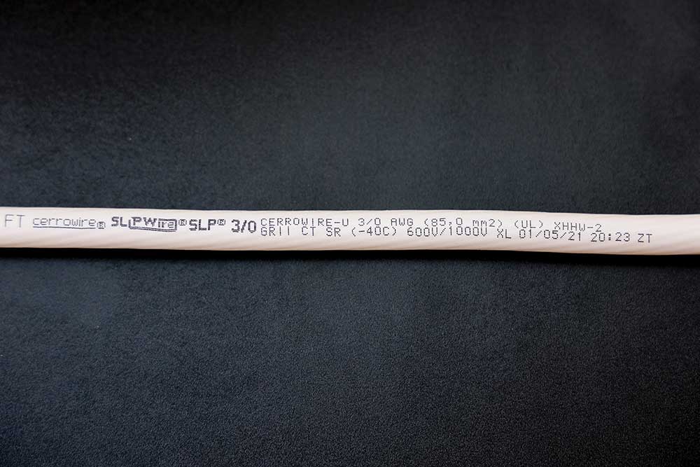
So, in this case, again, we have to say who the manufacturer is (Cerrowire), what the size of the conductor is (3/0 AWG), followed by the UL Listing mark. Just to be clear, UL publishes the product standard and can certify the products, but there are other organizations that can also certify these products. For example, Intertek, QPS, and MET Labs are some of the other laboratories out there. There are quite a few laboratories that have been accredited to certify electrical products. In photo 3, UL is the lab that certified this product.
Next are the type letters (XHHW-2), and if you look in Table 310.4(A), you will see that it includes XHHW-2. We used to have a note under the table that said, “-2” meant 90°C, wet or dry. A couple of cycles ago, we decided to go ahead and put the “-2” in the table itself, so you’ll see both XHHW and XHHW-2.
Notice the marking “600V/1000V”. Just in the last few years, we’ve added the capability for listing cables to 1000 volts. A lot of the reasoning behind this change is to address the need for higher than 600-volt ratings in renewable energy applications. For example, there are some wind turbines that have an output of 690 volts. There are solar PV installations that operate at 800 to 900 volts. So, we really needed that 1000-volt rating for those types of installations.
Some of the other optional markings you might see include something like the GR II mark, which means that it is oil and gas resistant. The I or II will tell you if it’s 60°C or 75°C. In this case, it’s oil and gas resistant at 75°C. CT means you can use it in a cable tray.
SR means that it is sunlight resistant. The “-40C” means it was subjected to a cold bend test at -40°C. Now, one thing I want to mention is that manufacturers typically don’t recommend that you install it at this temperature. For any insulated conductors, the recommendation from the manufacturers is to have cable at no less than (usually) -10°C for 24 hours before you pull it in. It helps avoid damaging the conductor, but it has been listed for cold bend at -40°C.
That XL means cross linked, which you will see on thermoset or crosslinked polyethylene conductors.
Example of Multiple Markings
Photo 4 is one that you’re probably all familiar with. It’s a THHN/THWN-2/MTW conductor. You’re probably more familiar with THHN than with any of the other markings, but I wanted to cover why we might have multiple markings on a conductor. So, why do we have THHN if we have THWN-2? Part of it could be specification and part of it could be that maybe you’ve got different installation areas where you want to put a conductor and different type letters meet different requirements. For example, MTW is a machine tool wire whereas THHN and THWN-2 are designations given to building wire that’s pulled into conduit. So, we use all of these different designations to cover a variety of installations wherever we can meet all of the requirements for all of those type letters.
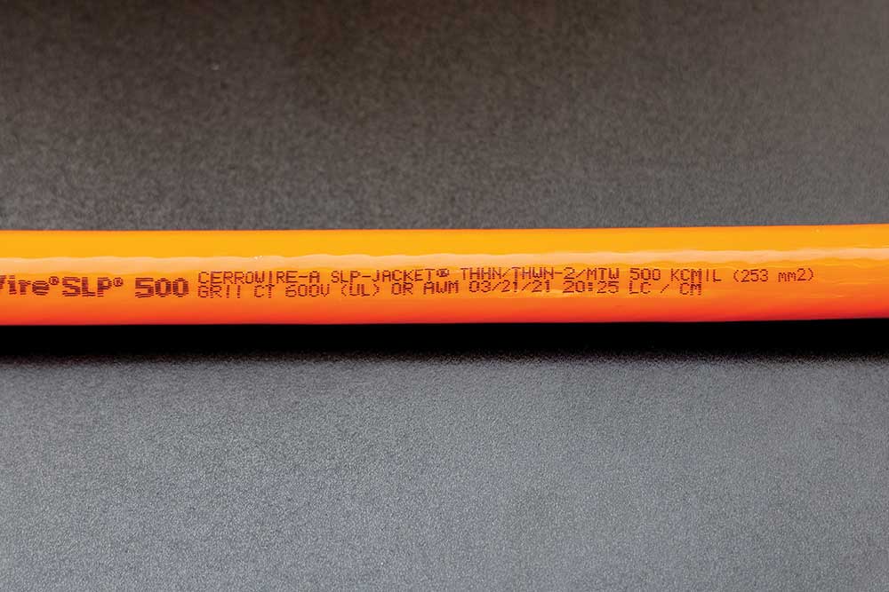
If you continue looking on the conductor, it shows 500 KCMIL. You might still see the term MCM used out in the industry. MCM and KCMIL mean exactly the same thing. KCMIL has been the preferred term for a couple of decades now in the wire and cable industry and in the codes. So even if you see MCM, it means the same thing as KCMIL.
Again, we have optional ratings (such as GRII). Thermoplastic installations of THHN do not have a 1000-volt rating at this time. So, you’ll only see them rated at 600 volts. In the last part where it says AWM, that stands for appliance wiring material, and you won’t find that in the NEC. There are dozens and dozens of different classifications of appliance wiring material that are certified according to UL standards that are used in appliance wiring applications.
So, here’s a knowledge check: Is THHN permitted to be used in a wet location? If the conductor is marked only with THHN, the answer is no. We looked at the conductor marking earlier, and it had multiple markings, but if a conductor is simply marked THHN, Table 310.4(A) would tell us that THHN is only permitted to be used in dry or damp locations. So, THHN by itself is not permitted to be used in a wet location.
That takes us through Part II of the newly re-organized Article 310 in the 2020 NEC. There is a lot of information in these articles, and it does take a while to absorb and understand it all. I do think that the updated organization now makes it easier to follow through the requirements. IAEI has a lot of training courses that can help you understand how to determine ampacity, use temperature and adjustment factors, and identify those conductors.
If you are interested in learning more about Article 310 and Article 311, you can watch the course online at iaeicourses.org.
This article is extracted from IAEI’s online training program entitled NEC Articles 310 and 311 by Christel Hunter on March 26, 2021. The full course can be purchased and viewed online at iaeicourses.org.