As inspectors who are required to perform inspections in a wide variety of construction projects, we frequently see customer-owned transformers installed in larger projects. These need to be inspected like all other parts of the premises wiring system, and they will often need corrections in order to make sure the installation is code-compliant.
So what are transformers, and why do we need them in our systems? Transformers are power conversion devices that allow us to change the operation voltages within our facilities. Keep in mind that when we use higher voltages, it allows us to use smaller conductors, conduits, and other related items which can mean a cost savings for the installation. For a typical building, anything we can run at higher voltages (like 480 volts and 277 volts) generally means savings related to wiring methods. However, most of our consumer electronics and utilization equipment is still based on 120 volts. Transformers are used to change voltages to the levels we need for utilization. Quite often, a building will be supplied at 480Y/277, and then a 480 volt primary to 208Y/120 volt secondary dry type transformer will be used. This allows motors to operate at 480 volts and lighting to be supplied at 277 volts, and we then transform that voltage to 208Y/120 volts for convenience use. There are many other examples of transformer use; some may step up voltages, others may buck (slightly lower) or boost (slightly raise) voltages.

So what are the things we need to look for when inspecting transformer installations, and what items in Article 450 apply to inspections? The first item in Article 450 we need to look at is 450.3 Overcurrent Protection. In 450.3(B) Transformers 600 Volts, Nominal, or Less, we are directed to use a table to provide overcurrent protection for typical transformers, Table 450.3(B). Notice first that the table is based on current values, with the first column at 9 amps or more; this is where we find values for the transformers we generally see installed in building construction. The table has two rows; the first row is used when only primary overcurrent protection is provided. As you can see in the table, it is limited to 125% with a note stating we can round up to the next standard size as per 240.6. The second row is for instance where we provide protection on both the primary and secondary side of the transformer; under these conditions we are allowed to move up to 250% on the upstream side and 125% on the downstream side. In other words, we provide double protection so that the primary is basically protecting the transformer itself, and the secondary protection is providing the required protection needed for the conductors being fed from the transformer.
Table 450.3(B) also covers transformers at lower current values. The smaller current transformers, such as 2 amps or less, are usually found in control cabinets.
One of the first things we need to check for when doing inspections is how the transformer is being protected and whether it is done correctly per the table. Often we find installations where they protect the primary at 250% and forget secondary protection. Generally, conservative design professionals call for both primary and secondary protection.
The next point of concern is Article 450.9 Ventilation. Here we find the requirement that we need to pay close attention to the ventilation requirements of the transformer and that this information should clearly be marked on the unit; sometimes you may have to read the small print.
Section 450.11 lists the marking information required by code. This is pretty self-explanatory, but if you have any doubts during an inspection, you can review this section. Transformers shall be readily accessible as per 450.13 to qualified personnel for inspections and maintenance. There are a couple of exceptions to this requirement, one being where the transformer is installed in open locations on walls, columns or structures. The other exception to this that I commonly saw in the field was installing a transformer above a drop ceiling. The details for this type of installation are found in 450.13(B), which limits the use of this exception to a 50 kVA transformer or smaller. When installed in these locations, we still have to maintain the ventilation requirements.

In 450.14 Disconnecting Means, we find the requirement for a disconnecting means to isolate the transformer from power. The disconnecting means can either be in sight of the unit or in a remote location, as long as the disconnecting means meets the required locking feature and there is a label on the transformer indicating where the disconnect is located.
The most common transformers we find during inspections of building construction are Dry-Type, and Section 450.21 gives us further information related to these depending on the size. If it is 112.5 kVA and smaller, the code requires a 12-inch separation from combustibles unless separated by a fire-resistant or heat-insulated barrier. When the transformer is over 112.5 kVA, the code requires that the transformer be installed in a room of fire-resistant construction, usually with a minimum of 1 hour rating. This is a building code requirement, so if in doubt as to the rating of a room, check with the Building Inspector for the site.
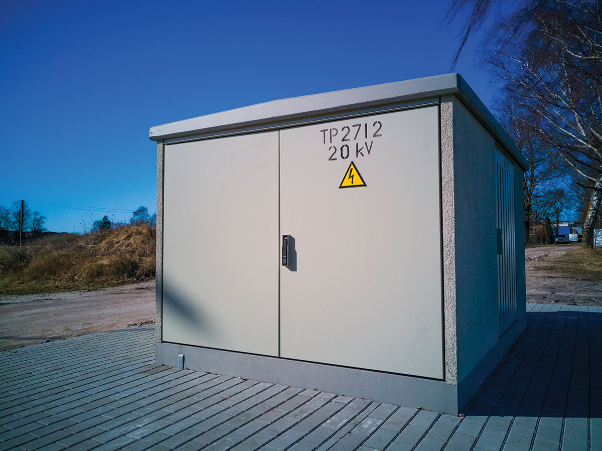
When we install a transformer outdoors, it must be installed in a weatherproof enclosure as per 430.22. This is quite often nothing more than a deflection shield for each side of the transformer, not a total enclosure such as those we see with exterior equipment that meets a NEMA 3R rating.
Now let’s review a few other requirements we have already covered in this series of articles that are very critical to the proper installation and inspection of transformer installations. First, we need to consider the transformer mentioned above that converts 480 volts to 208Y/120 volts, 3-phase; when we make this conversion, we have created a separately derived system. As we have learned in a previous article, we must apply Article 250.30, where we are reminded that we need a System Bonding Jumper. This is what gives stability to the neutral conductor of the new system; otherwise, the voltages will vary according to the loads on each phase independently. I always preferred this bonding jumper be installed as close as possible to the new source, which is inside the transformer. The transformer enclosure has room to make this installation much more cleanly than inside a crowded disconnect switch. Also, the proper sizing of the Supply-Side Bonding Jumper and the connection to the Grounding Electrode system are covered in Article 250.
When looking at transformers, we have code requirements related to the size and length of the secondary conductors. These requirements are located in 240.21(C), where we find the length of these conductors related to the application. The language provides us with the proper sizing rules, requirements for physical protection, and indicates that they must terminate into a single circuit breaker of set of fuses.
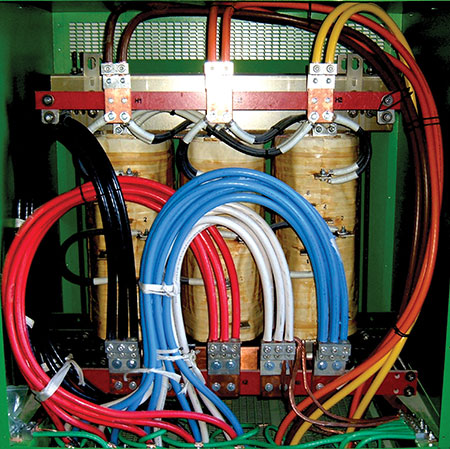
An installation item to be aware of when inspecting transformers is that the manufacturer will usually place a label inside with a line indicating that all conductors must be kept below the line. Many times the installers don’t see this note or they ignore it. It is part of the installation requirements for that unit and must be followed. As you can see, when inspecting transformers, there is more to know than solely the requirements in Article 450; there are many other requirements that apply.
I have to relate one of the most entertaining transformer installation stories I’ve ever seen. One day over a decade ago, one of my inspectors called to say he was inspecting a transformer that had a breaker-like switch inside of it, and he wasn’t sure what to do since the switch wouldn’t be readily accessible during operation (see photo 3). Once I got on–site, I found a transformer that had internal fans and thermocouples located inside. The idea was that as the transformer got hot, the fans would cool it; then if it started overheating, the enclosed breaker-like switch would simply shut down the transformer before it could overheat. It was actually a pretty nice idea and design, but this unit was located outside on the east side of a solid block masonry building, with direct sunlight exposure in the Las Vegas area. My first thought was that this would be shutting off on our really hot days, so we looked at the label and it had a reference to an installation document.

Once we got back to the office, we looked up the installation document and the language we found inside was as follows:
Adequate ventilation is essential for the proper cooling of transformers. Clean dry air is desirable. Filtered air at or above atmospheric pressure may reduce maintenance if dust or other contaminants present a problem. When transformers are located in rooms or other restricted spaces, sufficient ventilation should be provided to hold the air temperature within established limits (30C/86F average over 24 hours with a 40C/104F maximum) when measured near the transformer inlets.
As anyone who has spent time in Las Vegas during the summer will recall, we exceed 104 degrees F frequently, and often our overnight lows are well above the 90 degree F mark. I can remember playing ball games close to downtown Las Vegas after midnight and seeing temperature reading from the top of the hotels of around 102 to 104 F. Knowing this, I didn’t think this transformer was a good fit for an outdoor Las Vegas environment. When we notified the contractor of our decision, we weren’t very popular. Time was an extreme issue on this project; they had to get this big box store open. When the general contractor heard of the situation, they immediately took it upon themselves to create what they thought was going to be a solution to the problem, as you can see in photo 4.

When the design professional investigated and saw the transformer that the equipment supplier had specified, he agreed with my decision that it wasn’t the right fit for the installation. He then clearly specified a transformer that was rated for our local temperature conditions. As you can see in photo 5, this is an equally rated kVA transformer as the fan cooled unit; however, you can see it has a much bigger footprint to achieve the temperature rating requirements.

The moral of this story is that if the inspector hadn’t looked closely and been willing to ask questions, that facility very likely would have experienced power outages on a regular basis during the summer months. The inspector was brave enough to make this call and not just walk by it because he didn’t know what it was and didn’t want to look like he didn’t know everything about the electrical world. Remember, no one knows everything, we learn new things in the electrical industry on almost a daily basis.

Transformers are a very common item in electrical distribution systems, and knowing what part of the code applies to these installations is key to doing good inspections.





Find Us on Socials