
Selective coordination has been a requirement in the NEC since 1993 when it was first required for circuits with multiple elevators. Since then, additional critical systems have been added that require selective coordination. Healthcare facilities in NEC 2014 have established a different level of coordination from that found in other sections of the NEC. The essential electrical systems of healthcare facilities now have a minimum requirement of coordination which does not consider fault currents greater than the instantaneous pickup of upstream OCPDs. Separation of trip curves for times beyond 0.1 seconds is now a minimum requirement for these circuits. From the inspector standpoint, it is important to understand what is required to assure compliance; what devices are affected, what is needed to show compliance and how to assure the system is installed as designed. This article will address all of these considerations.
Definition
The first consideration for the inspector is to understand what selective coordination means. In layman’s terms, selective coordination is the ability to isolate an overcurrent condition in the electrical distribution system, by operating only the nearest upstream overcurrent protective device. The definition was added to the NEC in 2005 and modified in NEC 2014. The change in NEC 2014 was to replace “choice” with “selection and installation” and add a new last sentence to clarify that all overcurrents and all times must be considered.
Coordination (Selective). Localization of an overcurrent condition to restrict outages to the circuit or equipment affected, accomplished by the selection and installation of overcurrent protective devices and their ratings or settings for the full range of available overcurrents, from overload to the maximum available fault current, and for the full range of overcurrent protective device opening times associated with those overcurrents.
Where Required
Selective coordination is required for critical systems where system reliability is of primary concern. NEC 2014 requires selective coordination for multiple elevator circuits, emergency systems, legally required standby systems, critical operations power systems, critical operations data systems and campus style fire pumps.
NEC 2014 includes a new requirement in Sections 620. 62, 700. 28, 701. 27 and 708. 54: “Selective Coordination shall be selected by a licensed professional engineer or other qualified persons engaged primarily in the design, installation, or maintenance of electrical systems. The selection shall be documented and made available to those authorized to design, install, inspect, maintain, and operate the system.”
Summary of 2014 NEC Selective Coordination Requirements
620.62 Required for circuits with multiple elevators
700.28 Required for Emergency Systems
701.27 Required for Legally Required Standby Systems
708.54 Required for Critical Operations Power Systems
645.27 Required for Critical Operations Data Systems
695.3(C)(3) Required for Campus Style Fire Pumps
517.30(G) Requires Coordination (separation of curves beyond 0.01 seconds) of the Essential Electrical Systems in Hospitals
In addition, a new section, 700. 8, was added that required surge protection devices to be installed in or on all emergency panelboards and switchboards. It is important to note this applies to all emergency panelboards and switchboards, not just the first one.
Healthcare saw several changes during the NEC 2014 Code cycle in Article 517. The first was the deletion of the term emergency systems. Previously this encompassed the critical branch and life safety branch and created confusions, so the term and combination of the critical and life safety branch were removed. Further, section 517. 26 was revised to only require the life safety branch to comply with Article 700, previously it was the entire essential electrical system. A new section 517.30(G) was added which modifies the selective coordination requirement of Section 700.28 for the life safety OCPDs in hospitals. In hospitals, selective coordination is not required for the life safety (as well as critical and equipment) branches. The level of coordination has been determined, based on the performance requirements found in NFPA 99, to require separation of trip curves for times of 0. 1 seconds or longer without regard to fault current. These installations are not held to the same level of selective coordination as found in other sections of the NEC. However, selective coordination in these systems should be a design goal for the engineer.
Compliance – Which Overcurrent Protective Devices Are Affected
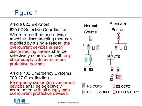
From the inspector standpoint, it is important to understand what overcurrent protective devices are affected by this requirement for selective coordination. To accomplish this, we first have to determine which overcurrent protective devices are affected. In figure 1, we show the text of sections 620. 62 and 700. 28 and an example of a partial electrical distribution system. The only portion we will be analyzing is the overcurrent protective devices supplying multiple elevators and emergency system overcurrent devices.
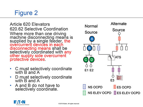
For elevators, we are concerned about the overcurrent device in the elevator disconnecting means and making sure this overcurrent device operates before anything upstream. However, selective coordination is not required for the upstream feeders. Figure 2 illustrates where selective coordination is required and not required for multiple elevators systems.
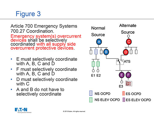
For the emergency system, we must assure all overcurrent protective devices from the load to the alternate source are selectively coordinated. However, we must also assure the emergency system overcurrent protective devices on the load side of the automatic transfer switches are also selectively coordinated with the normal source overcurrent protective devices. However, the overcurrent protective devices ahead of the automatic transfer switch on the normal side are not required to be selectively coordinated. Figure 3 explains where selective coordination is required, and where it is not required for emergency systems.
The design engineer has a choice on how to comply with the above; they can design with circuit breakers, fuses or a combination of circuit breakers and fuses. The next section illustrates what is needed to determine proper selection of the overcurrent protective devices.
Compliance for Healthcare
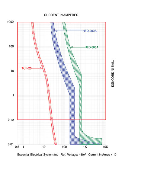
As mentioned previously, selective coordination is not required for healthcare per NEC 2014. Separation of trip curves for times beyond 0. 1 seconds without regard to available fault current is the new minimum requirement. Fault currents are not required to be considered for anything other than OCPD interrupting and equipment SCCR ratings. To confirm compliance with this new minimum requirement, the electrical inspector must verify separation of trip curves for times 0.1 seconds and longer. Fault currents greater than the instantaneous pickup of upstream OCPDs are not required to be considered. The engineer is encouraged though to go above and beyond the bare minimum requirement of the NEC to provide greater assurance of reliability for areas of the power distribution system that demand reliability for life safety reasons. As fault currents increase beyond the instantaneous pickup of upstream overcurrent protective device, the likelihood of cascading operation of OCPDs becomes greater. Figure 4, shows an example of a time-current curve. If this were an essential electrical system in a hospital, only separation of curves in the red boxed area would be required.
Selective Coordination Compliance for Circuit Breakers
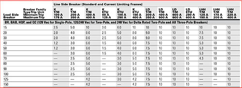
The application of circuit breakers will require determining the maximum available fault current at the overcurrent protective devices where selective coordination is required. This fault current must be calculated, and several programs can perform these calculations, some of which are free. Once the maximum available fault current is determined, the design engineer must select the circuit breakers and verify they are selectively coordinated up to the maximum available fault current. This is a two-step process; the first is to plot the time current curves and the next is to plot the maximum available fault current on these curves. There must be no overlap of curves at these available fault currents. For those circuit breakers that clear faster than 0.1 seconds in the instantaneous region, the available fault current must not exceed the instantaneous pickup of the upstream circuit breakers. When selective coordination cannot be determined by use of the TCC curves, manufacturer published selective coordination tables can be used. These tables identify the maximum short-circuit current to which a pair of circuit breakers selectively coordinate. Figure 5 shows an example of a circuit breaker selective coordination table. As an example of how these tables are used let’s consider a 20-amp BAB branch circuit device. Per this table, a 20-A BAB circuit breaker will selectively coordinate up to 8,000 amps when downstream of a K frame 400-A thermal-magnetic circuit breaker. Short circuit currents at the downstream BAB 20 circuit breaker greater than 8000 amps will result in both circuit breakers tripping. Selective coordination with circuit breakers is often an iterative process as selection of upstream circuit breakers may need to be altered to achieve selective coordination.
Compliance with Fuses
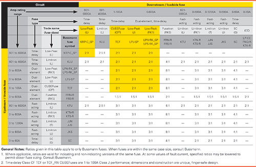
With current-limiting fuses, the selection process is much easier. To achieve selective coordination with current-limiting fuses, only the required minimum ampacity ratios for the given type of fuses are needed. Time current curves are not required for verification of selective coordination provided the minimum ampacity ratios are met. Typically, there is a family of fuses available from fuse manufacturers where the minimum ampacity ratio for selective coordination is 2:1. Therefore, as long as the upstream fuse is at least twice as large as the downstream fuse, selective coordination is achieved for all short-circuit currents up to the interrupting rating of the fuses. Figure 6 shows an example of a current-limiting fuse selective coordination ampacity ratio table.
Compliance with Circuit Breakers and Fuses
In some systems, it is beneficial to use a combination of fuses of circuit breakers. Placing current-limiting fuses downstream of the circuit breakers can provide selective coordination to higher levels of short- circuit currents than circuit breaker only applications. To confirm compliance, some manufacturers offer selective coordination tables of circuit breakers and fuses with maximum fault currents indicated up to which selective coordination is achieved. In most cases, the maximum short-circuit current shown is the interrupting rating of the upstream circuit breaker. An example is shown in figure 7.
Automatic Transfer Switches
The automatic transfer switch presents a unique challenge to the engineer in selectively coordinated systems. Automatic transfer switches have short-circuit current ratings (also called a withstand and close-on rating or WCR) that must be considered. The adequacy of the ATS with regard to this rating will depend upon the type, rating, and setting of the upstream overcurrent device. The clearing time of the upstream OCPD for fault currents at the transfer switch must be determined and compared with the capability of the transfer switch. The inspector must verify that consideration was given to the type and settings of the selectively coordinated upstream overcurrent device ensuring that the selection results in a short-circuit current rating (SCCR) of the automatic transfer switch that is adequate for the maximum available fault current at the automatic transfer switch. NEC 2017 will include a marking requirement that will help the inspector determine the proper application of automatic transfer switches. NEC 2017 will require the field marking of the ATS SCCR, based on the upstream overcurrent protective device.
Electrical System Studies
A short-circuit and coordination study, or other documentation, is required to help ensure compliance with selective coordination requirements. These studies are often completed by a third party. Proper documentation could be as simple as use of selective coordination tables as shown above for fuse applications or very detailed studies that include calculation of short-circuit currents and plotting time-current characteristic curves. Either way, documentation must be made available to all parties involved. Where a short-circuit and coordination study is performed, several parts are typically included:
- Short circuit study
- Equipment Evaluation
- Selective Coordination Evaluation
- Coordination Study
- Arc Flash Analysis
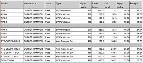
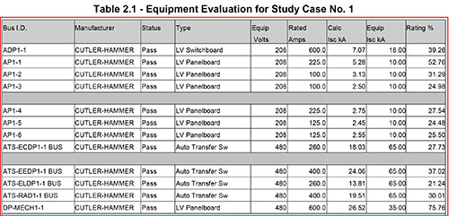
The short circuit study will determine the maximum available fault current at each overcurrent device and electrical equipment. The equipment evaluation, as shown in figure 8, assures compliance with NEC 110. 9 for proper interrupting rating of overcurrent protective devices and NEC 110. 10 for proper equipment SCCR. This evaluation is required for every installation, not just systems where selective coordination or a level of coordination is required.
The selective coordination evaluation for circuit breakers or circuit breaker and current-limiting fuses includes the evaluation of time current curves and proper separation of curves as well as a pass/fail check of the manufacturer selective coordination tables. Where current-limiting fuses are used to achieve selective coordination, verification of the minimum ampacity ratios per the manufacturer selective coordination tables is all that is required for the fuses used in the critical system.
For some systems, additional studies may be requested. For instance, the balance of the electrical distribution system, where selective coordination or a level of coordination is not required, a coordination study may be requested. This study determines the proper settings and ratings for the overcurrent protective devices to achieve the best degree of coordination for the overcurrent protective devices selected. Finally, an arc flash analysis may be included to determine the incident energy at the electrical equipment that is likely to require servicing or maintenance.
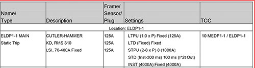
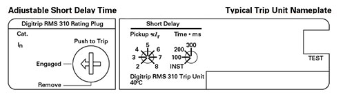
Installation
The final consideration is to assure the equipment is installed per the electrical system study. This assurance is especially important where circuit breakers with adjustable trip units are used. The study should indicate the required settings for the adjustable trip circuit breaker so the installer knows what settings should be utilized. This knowledge is important for all adjustable trip circuit breakers, not just where selective coordination or a level of coordination is required. Figure 9 shows an example of the required settings for an adjustable trip circuit breaker and the how to adjust the circuit breakers setting.
Conclusion
Selective coordination is an important requirement for critical electrical systems. The electrical inspector does not need to know how to determine what overcurrent protective devices are required to achieve selective coordination for critical systems. However, the electrical inspector does need to know the process and what is required to confirm compliance with the requirements for selective coordination. In addition, documentation of compliance for selective coordination requirements must be made available to the AHJ for their records as part of the approved documents for the project. This typically requires an electrical system study, often by a third-party to be completed and made available to all needed parties in addition to the AHJ. It is also important to understand what is required; selective coordination for all currents and all times or coordination, separation of curves for times greater than 0. 1 seconds for hospitals. Finally, the electrical equipment must be installed per the electrical system study, which is especially important for adjustable trip circuit breakers.