Let’s take a look at some of the more significant changes impacting photovoltaic (PV) installations once the 2020 National Electrical Code (NEC) is validated by the NFPA Standards Council. These changes can be found in Article 690, Solar Photovoltaic (PV) Systems. Additional PV-related changes are located in Article 705.
Article 690
The first items are some relatively minor changes made to Figures 1(a) and 1(b) located in the informational note to Section 690.1. These changes reflect current technologies and properly correlate nomenclature that is either used elsewhere or not used at all. One example is the removal of the word “Panel” in the figure that points to a cluster of modules as that term is no longer used in the industry.
The first substantive change was in the rearrangement of Section 690.8 and the addition of 690.8(A)(2). The basic requirement that has been used for many years is that the maximum circuit current for a PV circuit is based on the maximum available output of the PV modules as corrected for irradiance. The new language allows the circuit current to be determined by the rated input current of the conversion equipment (usually an inverter). The other part of this new requirement is that the conductors must be protected by an overcurrent device rated not more than the circuit conductor ampacity.
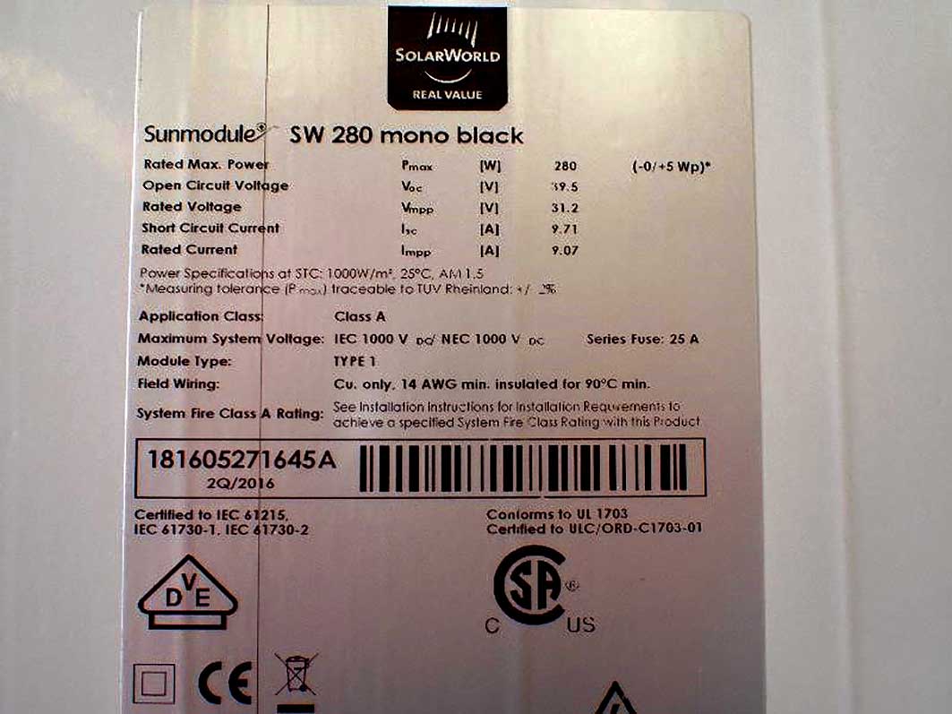
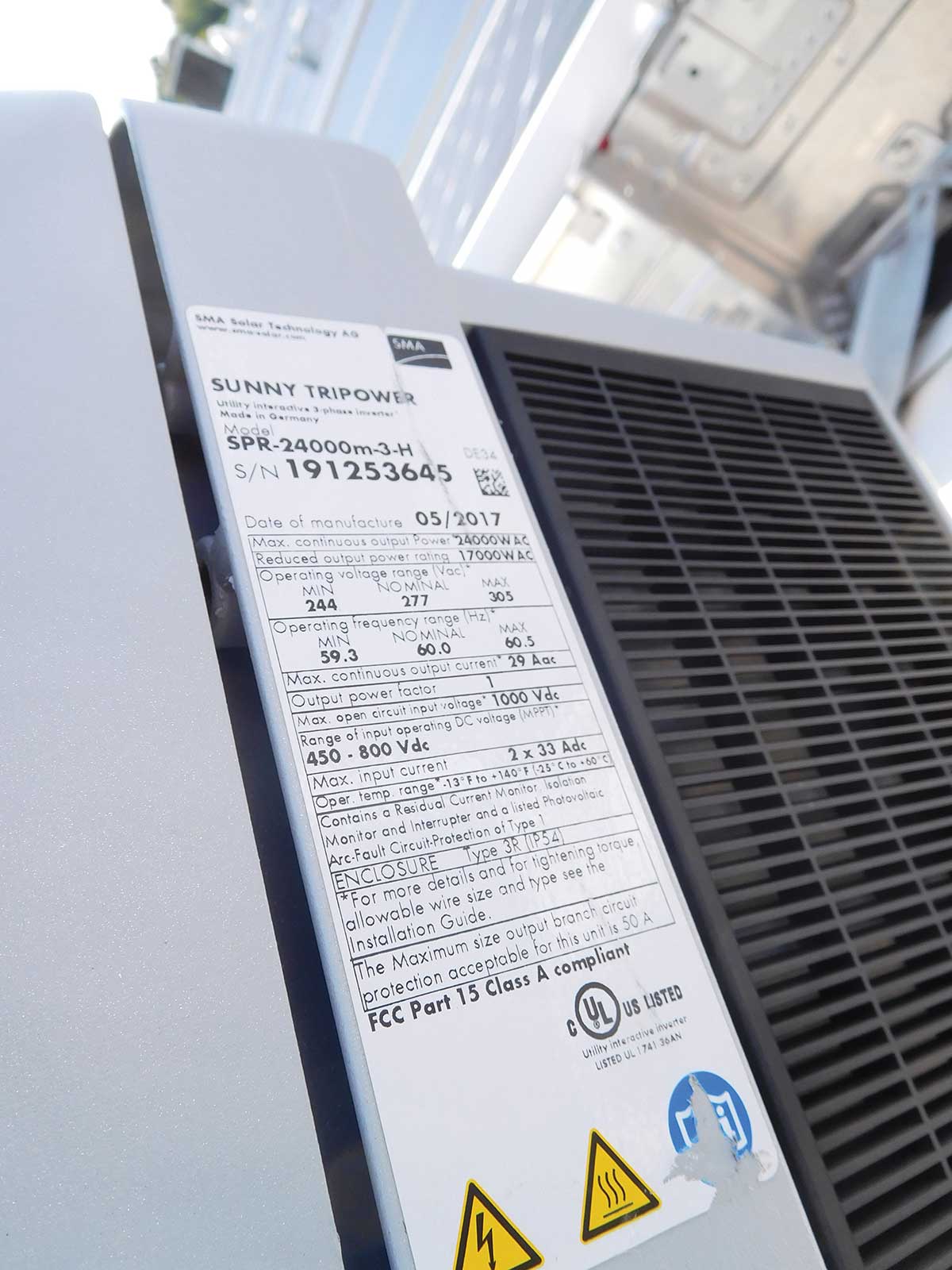
Let’s say, for example, that there are six strings of 280-watt modules supplying a 24 kW inverter as shown in photos 1 and 2. If each string has a maximum current of 12.1 amperes (9.71 A x 125%), then the combined output of the six strings would be 72.6 amperes according to 690.8(A)(1). Assuming 75°C terminals are used in the equipment, this requires a minimum of 4 AWG copper conductors. Using the new permissive language in 690.8(A)(2), you could use 8 AWG copper conductors protected with 50-ampere fuses to supply the inverter input current of 33 amperes x 125% (continuous duty) or 41 amperes.
That is a reduction of two standard conductor sizes, which is less than half the amount of copper as required by the standard sizing method. While this most likely will not come into play in a residential system; however, in a large ground-mounted system, this could lead to substantial savings in copper conductor and conduit sizing.
(Author’s Note: The values above are based on the actual labels shown in photos 1 and 2. It is anticipated that equipment manufacturers will make modifications for this new permissive language, and the labels will reflect such. Also, conditions of use are not reflected in this example but would have to be reviewed in an actual installation).
The next substantive change was made in Section 690.9. In the 2017 NEC, 690.9(A) consisted of one paragraph with two exceptions. For the 2020 NEC, most of the same requirements remain in place but are stated in three separate list items and the language adds clarity. New Section 690.9(A)(3) addresses installations where conductor overcurrent protection can be provided at either the supply end or the load end of the circuit. These new provisions provide length limitations to be complied with, and where installed in a building, physical protection must be provided by metal raceways or cable armor. This is similar to the tap rules of 240.21 but without a tap. An example would be a ground-mounted array where the PV output circuit entered a building, and the overcurrent device for this circuit is located within the disconnecting means located at the load end inside the building.
Section 690.12, dealing with rapid shutdown of the PV system, also has extensive changes. Conductors that are considered outside the array boundary, as defined in 690.12(B), are those that are 1 foot from the array in all directions. These requirements have not changed. The requirements for inside the array boundary, as defined in 690.12(B)(2), have been changed to align with the product standard that is being developed by Underwriters Laboratories (UL). The new UL 3741 standard recognizes these systems as “Hazard Control” systems. That terminology is incorporated into the requirements found in 690.12(B)(2)(1).
At the time this article was written, the new standard was close to being finalized and submitted to the UL Standards Technical Panel (STP) for a vote. Once this standard is accepted, and products are developed, the installer will still have three choices: a system that is listed to UL 3741; a system that reduces the voltage within the array to 80 volts within 30 seconds; or a totally isolated system with no exposed wiring methods or conductive parts such as integrated roof shingles that constitute a PV system.
Language added to Section 690.13(A) states that if a PV system disconnecting means is installed in a location where it is readily accessible to unqualified persons, and the conductors are energized at 30 volts or more, the disconnecting means will then be required to be so constructed that a lock can be installed to limit accessibility or a tool is necessary to open the disconnecting means. This requirement accomplishes the intended provision of limiting unintentional contact with energized parts through the use of a lock or a tool.
Section 690.13(E) was changed to reference 110.25 and now requires a PV system disconnect to be locked. It extends the requirements to remote operating devices that are used to control the disconnecting means. Also, the type of disconnecting means to be used was put into a list format as List Items (1) through (5).
The general thought process for addressing the requirements for disconnecting means was to make it clear that the requirements located in 690.13 are intended to address how a PV system is isolated from all other systems in a building or structure. Section 690.15 will address the isolation of PV system equipment for safety purposes when servicing equipment. It should be noted that there will be times when a single disconnecting means could be used to satisfy both requirements.
The main body of 690.15 directs you to 690.15(D) for the type of disconnecting means that is permitted to be used for isolating equipment. There is also a change at 690.15 that removes PV modules from the list of equipment requiring a disconnect for isolation purposes. The rationale for this change was that in some PV systems, the listed modules include a junction box and are direct wired. In these cases, the string would have an isolation disconnect but not each module. This does not prevent someone from installing modules with listed connectors and continuing to use them to isolate the modules individually rather than at the string level.
Section 690.15(A) was also modified to add the requirement of requiring a lock or a tool to open if accessible to unqualified persons. The remainder of the changes in 690.15 were really just reorganizing the existing requirements into a more user-friendly format. By the way, not a change but for the sake of clarity, an externally operable disconnect does not mean that it must be located external to the building. It means that it is operable without exposing the person operating it to energized live parts.
Section 690.31 contains several changes. The first change is in 690.31(A), where the table has been changed to recognize correction factors that can be used when ambient temperatures exceed the values given in Table 310.16 [previous Table 310.15(B)(16)], and conductors that have higher temperature ratings are used. This change may not encompass all conductors that are rated at higher temperatures. For those instances, engineering supervision and/or manufacturer’s instructions will be necessary. This change also added Table 690.31(A)(b) for the ampacities of some high temperature rated conductors.
Changes were made in 690.31(B) to recognize integrated Class 1 circuits being placed in raceways and cable systems also used for PV system DC circuits. An exception to the separation requirements was also added for jacketed and metal clad cable assemblies with a restriction of being rated for the highest voltage available for all of the contained circuits.
Section 690.31(B)(1) was modified to mandate a marking scheme for PV system conductors that consists of either color coding or labeling to consist of either “+,” “POSITIVE,” or “POS” symbol for the positive conductor and either “-,” “NEGATIVE,” or “NEG” symbol for the negative conductor. This, of course, would change to the marking required for a grounded conductor in Section 200.6 if the system contained a solidly grounded conductor.
Section 690.31(C) now recognizes listed Type DG (Distributed Generation) cable as a recognized wiring method and the terminology for “Sunlight Resistant” was modified slightly for better alignment with the product standards (UL 4703, Standard for Photovoltaic Wire, for PV wire and UL 3003, Distributed Generation Cables, for DG cable). The other change in this area at 690.31(C)(1)(2) was to recognize a distance of 24 in. between supports for single-conductor cable rather than the previous requirement to comply with 334.30 (12 in.). The previous support requirement of 12 in. for module junction boxes was too close to allow the removal of modules. The 4½ ft spacing between supports permitted by 334.30 was too long and allowed conductors to sag too much. The use of multiconductor jacketed cables is covered in 690.31(C)(3). These cables are limited to the rooftop area unless contained in a raceway and listed for the application. It should be noted that there are also support requirements for these cables and language that permits their use underground as long as they are listed for underground installation.
A rather small change but one that is worthy of consideration is in 690.33(C) where a sentence was added to address the “intermatability” of connectors used for connection and splicing of PV conductors. This has become a real concern and one that has led to fires in existing installations. Of course, the question remains, was it the lack of matability of the connectors or the installation process? In either event, this new “intermatability” requirement will add an additional layer of safety similar to classified circuit breaker requirements.
Section 690.41(B)(1) added a sentence and an informational note relative to ground-fault protection in a system that utilizes DC to DC converters. These devices are becoming very common and do a very good job of regulating the system to provide maximum power output. Many of these DC to DC converters are also being used as rapid shutdown or hazard control devices and they function very well for that purpose. The problem addressed at 690.41(B)(1) is the fact that these devices are inserted between the modules and the conversion equipment and may actually block the recognition of a ground fault. This will have to be addressed with the equipment manufacturer.
The requirements in 690.56(C) for the labeling of buildings with PV systems and “Rapid Shutdown” have been modified to reflect the delayed implementation date of January 1, 2019, that appeared in the 2017 NEC. The labels will now read as follows: “SOLAR PV SYSTEM IS EQUIPPED WITH RAPID SHUTDOWN. TURN RAPID SHUTDOWN SWITCH TO THE ‘OFF’ POSITION TO SHUT DOWN PV SYSTEM AND REDUCE SHOCK HAZARD IN ARRAY.” The title of the remaining figure has been changed to identify this figure as an informational note figure to clarify that the label as shown is merely an example of a rapid shutdown system label. Other label arrangements and/or diagrams are acceptable.
It is still required to have placarding and a diagram if the building has more than one type of system. This placarding is required to be placed at each service equipment location. This could cause confusion and better clarity will most likely have to be added as “Service Equipment” by definition encompasses more than the service disconnect. This was discussed and the general sentiment was that this language sufficed and people are always encouraged to submit a Public Input if they believe that different language such as “Service Disconnect” should be used.
Article 705
Now on to Article 705. The first item to recognize is the title to Article 705, Interconnected Electric Power Production Sources. By the title, one can see that it is not limited to PV but any onsite power production source that is intended to interconnect with a utility power system. Similar to the restructuring of Article 690 in the 2017 NEC, which reduced the text of that article by 30%, a restructure of Article 705 occurred in 2020 NEC which reduced the article a similar amount. Previously, there was a whole separate Part II for Interactive Inverters and Part III for Generators. The requirements found in these two parts were consolidated into Part I to address all types of power sources and make it simpler to find the requirements.
The first item to be looked at here is a definition of Power Source Output Circuit. It is defined as “the conductors between power production equipment or a power source and the service or distribution equipment.” This definition is intended to better describe what was formally referred to as an inverter output circuit as these conductors may or may not be from an inverter output solely.
A new Section 705.11 was created to better define the installation of a supply-side disconnecting means, grounding and bonding requirements, conductor sizing, and wiring methods when interconnections are being made ahead of the service main disconnecting means as permitted in 230.82(6). This section is subdivided from 705.11(A) to 705.11(G). However, that will have to change as a Certified Amending Motion (CAM) was presented for 705.11(D), Bonding and Grounding, and 705.11(F), Disconnecting Means. Both CAMs were passed on the floor of the NFPA Annual Meeting. After the anticipated results of the CMP-4 re-ballot on this issue, the anticipated effect is that both of these subsections will disappear and Code language will default back to the previous version of the 2017 NEC. Unfortunately, 705.11 did not exist in 2017. Thus, they will simply disappear. Of course, Tentative Interim Amendments (TIAs) could also be submitted on these requirements so stay tuned to the NFPA web site at www.nfpa.org/70next for any actions taken on the 2020 NEC. The bonding and grounding requirements are anticipated to revert back to 250.25, which refers back to 250.24. In the opinion of this author, this will continue to create confusion in the field for installers and inspectors alike.
The new 705.11(B) introduces a minimum conductor size of 6 AWG copper or 4 AWG aluminum and requires wiring methods meeting the requirements of 230.30 (underground service conductor installations) or 230.43 (wiring methods for 1000 volts, nominal, or less). The new 705.11(C) establishes conductor length limitations where the power source output circuit conductors make their connection to the service inside a building depending on whether the connections are made in a dwelling unit or other than a dwelling unit. It is important to note that just like the tap rules of 240.21 (even though these are not taps and the tap sizing rules do not apply), the length specified is total conductor length not the distance between enclosures or the length of a raceway.
A new Section 705.13 defines the installation requirements for “Power Control Systems.” These systems are already listed and in production by several manufacturers. Power control systems are intended to monitor and control multiple power sources, such as utility supply, energy storage systems, PV systems, and others while properly controlling these systems for optimum energy conservation. They also prevent overloading of any interconnections, whether made ahead of the service main or through the bussing of a panelboard.
The last change is in Section 705.20. This section was reorganized to encompass many of the various requirements for disconnecting means that were located throughout Article 705 and the requirements were put in one area for better usability. This section now covers the type of disconnecting means, simultaneous opening of all ungrounded conductors, ready access, external operability, the requirement for a tool to open if accessible to unqualified persons, indication (ON and OFF), ratings, and caution labels (if both sides are energized) all in one location.
I hope that you have enjoyed and learned something from this preview into the 2020 NEC for PV-specific changes. Of course, there is much more to learn from the IAEI’s Analysis of Changes, NEC-2020 book when released in August of this year and better yet, by attending an IAEI seminar or upcoming IAEI section meeting program on the changes to the 2020 NEC.



Find Us on Socials