Climate change will have both long-term and short-term impacts on the PV Industry in the areas of PV system installation, performance, and inspections.
In the long term, the consensus of most scientists involved in climate change research is that the average global temperature will increase if greenhouse gases continue to be emitted into the atmosphere. This is a slow process, but the effect on PV systems using the current technology will be to decrease the energy that the PV system can produce as the temperature increases. This is a straightforward consequence of the fact that the module peak power production is an inverse function of temperature. As the ambient temperatures increase during the day, the power and energy produced goes down. New technologies in PV module development may offset some of this power loss, and it’s possible that a practical PV module will be developed that can accept and produce power from both light from the sun and the temperature of the module itself.
In the short term, one must look at local weather conditions or monitor the national weather conditions on Weather.com or the Weather Channel and see that local environmental conditions are changing significantly throughout the country (and the World) and, in most cases, in most locations, becoming more severe. Seasonal temperatures are increasing in the Summer and decreasing in the Winter. Storms, both snow and rain, coupled with high winds, are becoming more intense and longer lasting. These changes in the weather patterns have a direct impact on the installation of PV systems and the inspection of those systems. Aside from the fact that severe storms prevent working in or inspecting PV systems in those environments, the changes overall, even on sunny days, can impact the longevity and probably the performance of PV systems. This is a situation that requires focus on the details of the PV installation, and some of those details will be covered in this article.
Details, details, details
The PV module. The PV module is tested by Underwriters Laboratories (UL) or another nationally recognized testing laboratory (NRTL) for mechanical durability under specified wind and snow loading conditions. The testing is done using holes drilled in the back frame of the module or using listed top clips, which secure the module to the supporting rack without using these holes. When a racking system is used, it should be listed according to UL Standard 2703, which details the structural and electrical requirements of the rack. The assumption is that the rack is firmly attached to the supporting structure, usually a roof or the earth, in a ground-mounted system.
The racking system. The wind loading used in testing the modules is based on established wind loads from various locations in the country, and the worst of these is used. Unfortunately localized severe weather conditions may result in wind loadings higher than these historically established wind loads. This is the first area where the installation of the PV system and the inspection of that PV system may require additional attention. Instruction manuals for the racks generally require that the racks be bolted to the roof using bolts that penetrate the roof sheathing and enter the rafters underneath the sheathing. In many parts of the country, sheathing may be as thin as ½ inch to 9/16 of an inch, and connecting the racking directly to the sheathing may not provide secure attachment points. Other types of mounting structures using specialized devices can be used to secure the modules to properly installed standing seam metal roofs. If the module manufacturer’s and the racking manufacturer’s specific instructions are not followed, the array may not be firmly attached to the supporting structure and will fail even at lower than the standard winds. Winds in severe weather conditions may exceed the standard winds, and if the building is not destroyed (tornadoes, snow loading, hurricanes, etc.), the PV array should generally remain attached to the structure when the structural attachment system is carefully designed and installed.
On ground and roof-mounted tracking arrays, the tracking system should have a wind stow provision that monitors windspeed, and when gusts exceed a certain value, the array is automatically moved to a horizontal position (pointing straight up). This will minimize the loading on the modules, the racking system, and the supporting structure in extreme weather events. Since these winds may occur anytime over a 24-hour period, the system should also work at night.
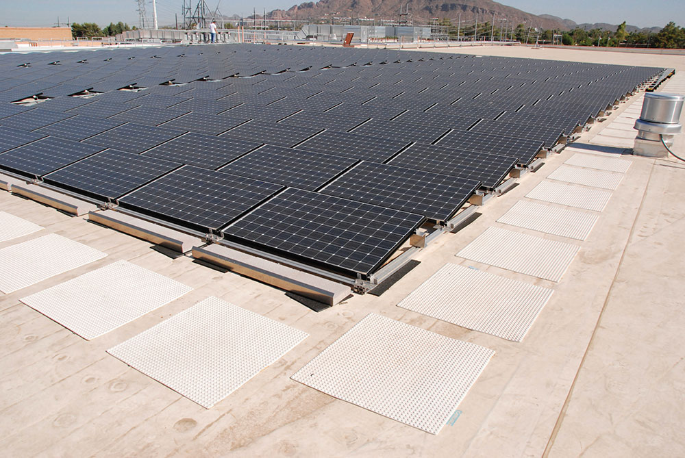
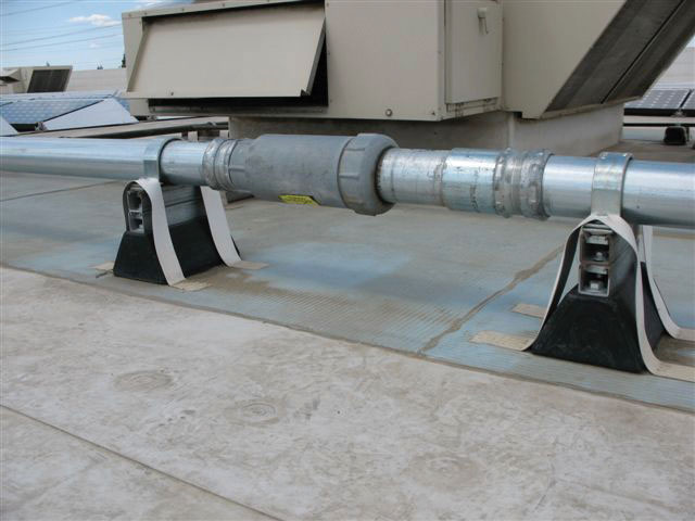
On commercial flat-topped roofs, the array may be mounted using concrete ballasted racking systems to hold the array to the roof by gravity. See photo 1. The weight of the ballasts should be calculated using the higher wind loading that may occur during severe weather events. Also, the underlying roof structure should be assessed with the heavier loading from the increased weight of the concrete blocks.
These issues require additional attention by the PV installer and by the AHJ during the inspection process. The inspector should query the installer on how the rafters were located under the finished roof and ask to see the tool or instrument used to make this determination — usually a stud finder. Calculations should be reviewed that show the structural loading of the roof. The attachment method and materials used should meet or exceed the manufacturer’s requirements.
In addition to wind loading, both downdrafts and updrafts, in areas where heavy snowfalls may occur, the condition of high point loading from the rack to the roofing structure should be considered. Snow on a plain (no PV array) roof is distributed throughout the roof. However, when a PV rack and modules are installed, the snow loading on the PV modules is concentrated through the attachment points on the rack to a point loading system on the roof. Such high-point loadings may cause the roofing structure to fail. The racking instructions should address this issue and recommend appropriate spacings on roof mounting points.
Ground-mounted PV arrays. Ground-mounted PV arrays should have the earth attachment points firmly anchored, and where necessary, a soil analysis should be conducted to determine the necessary depth of the racking legs under very high wind loads that may occur during severe weather events.
When using stainless steel nuts, bolts, and other mounting hardware, an anti-seize compound should be used on all threads to facilitate future removal for repair or replacement.
Array conductors. The conductors from the PV module to the combiners or the inverters must be carefully sized and installed. These conductors should be of the highest quality available and meet National Electrical Code (NEC) requirements. Cross-linked polyethylene conductors, such as those used for listed PV cable/PV wires, have shown to be the most rugged conductors commonly available. As temperatures increase locally during extremely hot weather, the temperatures used for calculating the ampacity of the conductors and their size must be carefully considered to address these higher temperatures. If higher temperatures are not addressed, the conductor may suffer premature aging and failure. The temperature of the conductors should also be adjusted for solar heating if they are installed within 3/4 inches of metal supporting structures in sunlight [NEC Section 310.15(B)(2)]. Also, where possible, adjustments should be made for higher-than-historical normal ambient temperatures that can occur during future expected increasing temperatures.
Exposed conductors throughout the PV array should be firmly secured to the supporting structure. High winds can cause small movements of conductors, which can rub against the supporting racking structure and cause insulation failures. This situation was noted during inspections of ground-mounted PV arrays in the Southwest. Furthermore, these exposed conductors should not be routed to cross the sharp edges of the racks and should not be bent in a tight radius, which might cause insulation failure.
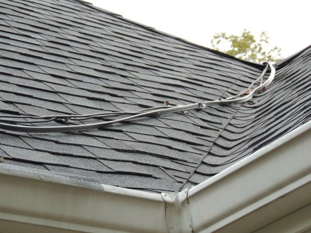
Conductors routed across the roof should be in one of the approved raceways, and those raceways should be firmly secured to the roof to avoid damage from winds, sliding snow, or sliding ice. See photo 2. The ends of conduits used for this purpose should use cable fittings (cord grips) that prevent water from entering the conduit. See photo 3.
Any splices in exterior conductors or in enclosures in an exterior location should be made with splicing devices and materials that can withstand the outdoor environment. Winds can drive rain into poorly constructed splices and into ventilation holes in enclosures that have such ventilation. Moisture at the connection location can cause corrosion and connection failure.
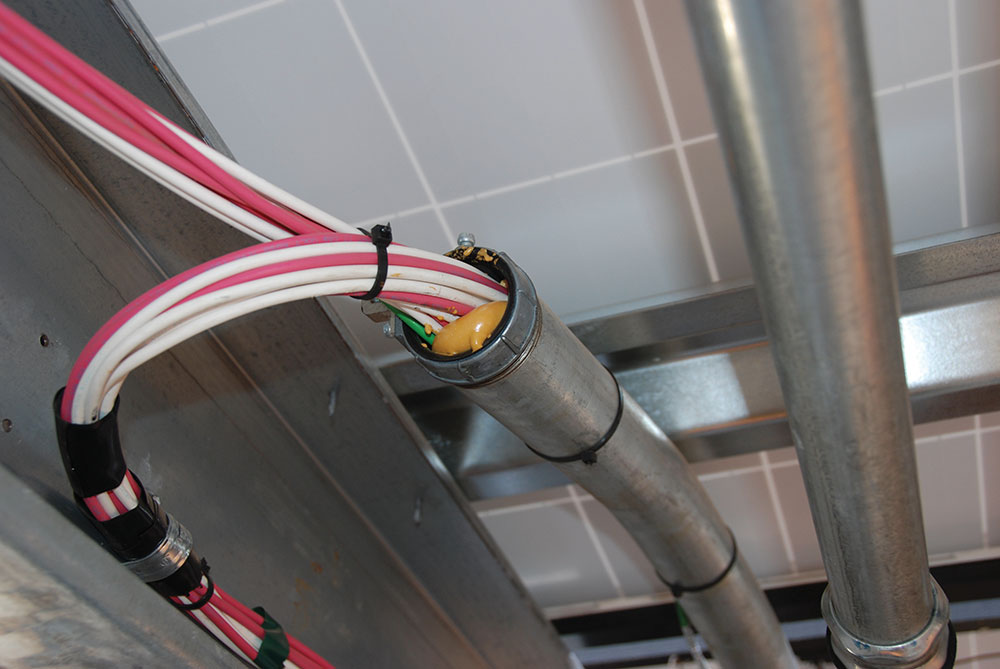
Long runs of metal raceways across the roof of a commercial building should be securely fastened with the proper supports that will allow linear expansion of the conduits, and the conduits should include expansion joints used to address the higher temperatures that may be encountered during extreme weather events. See photo 4.
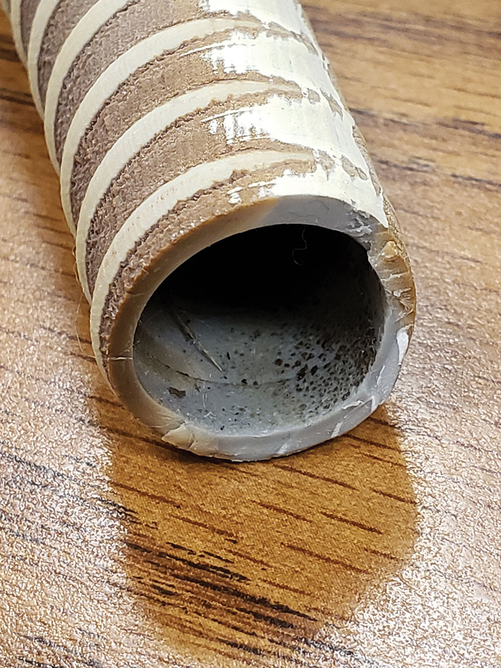
As an added note and in my opinion, the use of flexible PVC conduit (LFNC) should not be used outdoors were exposed to direct sunlight. Even though listed for sunlight resistance and outdoor rated, these conduits have been known to suffer sunlight damage in a few short years, becoming rigid and no longer flexible. See photo 5. Wind and ice loading can result in possible breakage of these conduits.
Electronic equipment. Devices such as DC PV combiners and fuse holders installed in cables should be installed in areas that are shaded from direct sunlight. Direct sunlight and high ambient temperatures can cause the interior of these enclosures and fuse holders to exceed the temperature rating of the enclosed overcurrent devices causing them to nuisance trip or blow. Note the required PV listed overcurrent devices are evaluated for a maximum temperature of 50° C. Ambient temperatures in the 45 to 50° C range plus direct solar heating on the enclosure can raise the interior temperature above 50° C maximum temperature of the internal and cable-mounted overcurrent devices. Such high temperatures would violate the listing on the overcurrent device in addition to causing unwanted blowing or tripping.
Where possible, inverters and any other electronic equipment should be installed in conditioned spaces and not in direct sunlight. Two issues may occur when inverters are installed in areas exposed to direct sunlight. One is an internal rise in the inverter temperatures when the ambient outdoor temperatures approach and exceed 40° C, and additional heating is provided by the direct solar exposure. High internal inverter temperatures will cause the inverters to protect themselves by reducing the output power and additionally, electronic components may suffer shortened lifespans. The other issue is that displays on these inverters, which are exposed to direct sunlight, may darken in a few short years and become unreadable.
Where it is not feasible to install electronic enclosures in shaded areas, adding ventilated shading panels around the device should be considered. These panels should be installed on the top, east, west, and south sides of the device and spaced to allow proper ventilation of the enclosure.
Increasing numbers of severe storms will result in higher numbers of battery-back-up PV system installations. The installation of these newer battery-backed-up PV systems that have wall-mounted inverters and battery banks should be done carefully following the manufacturer’s instructions. Some of these installations can weigh 400-500 pounds when mounted on the wall. If the wall is not structurally sound enough to carry that weight, then it may be damaged. Careful inspection of the wall and its integrity should be accomplished before mounting any heavy equipment on it. Some interior walls may have 2X3 inch studs rather than the more normal 2X4 or 2X6 inch studs. Reinforcement of the wall may be required. This can be accomplished by installing a sheet of ¾ inch plywood over multiple studs and then installing the equipment to the plywood. A careful analysis of the reinforced wall should be made before mounting the equipment. Any indication of the wall moving or sagging when a weight equivalent to the equipment weight is placed on the wall would indicate that the wall should be further reinforced or the equipment be mounted in another, more secure location.
Summary
A PV system that withstands severe weather events when the utility power has been knocked out and where a battery-backed-up system has been installed will be invaluable in keeping the home warm or cool and in keeping refrigerators and freezers operating as well as keeping the lights on and other appliances operating.
Where the structure of the house or commercial building remains intact, and the PV system has been carefully designed and installed to resist severe weather events, the home or building remains a livable habitat that can provide protection from the elements. Careful attention to numerous details in the design, installation, and inspection of the PV system is required to achieve this result.