Today’s demand for attention has brought on the need for signs to be more than just a display. Theses signs are designed for the potential customer to notice them and come in to check out the establishment. The sign might be portraying a message. Or it could be a show in itself. Let me take you on a quick step-by-step tour to inspecting signs.
Be aware of the codes
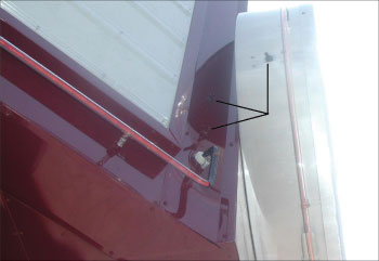
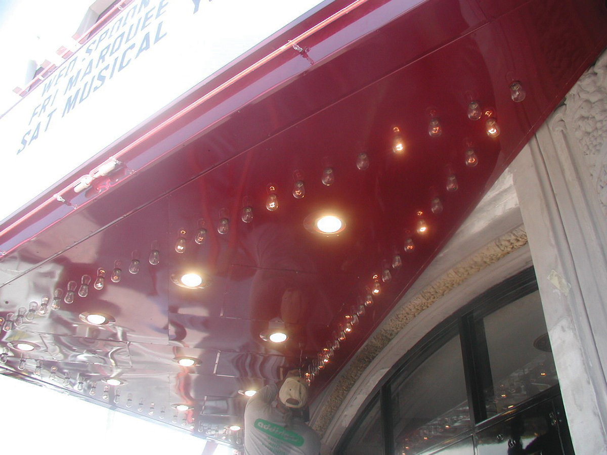
First, we inspectors need to be aware of the codes that affect the installation of signs (NEC Article 600), but also we might have other issues involved. Locally, one of the sign shops was contracted to recreate a theater marquee (see figures 1 and 2). This now incorporated some unique design criteria—such as luminaires, controllers, fluorescent cabinets, neon power supplies, and display lamps—and included compliance with additional code articles.
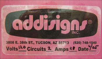
Is the sign listed?

Check both grounding and bonding
Grounding! This can be a whole other subject. Section 600.7 is where we look for grounding requirements for the sign, but don’t forget Article 250. Is that enclosure or raceway bonded? Section 250.148 reminds us that if circuit conductors are spliced, we need to bond the metal enclosure to the equipment grounding conductor. Do we have a good connection for our bonding connection to the power supply cabinet under the painted surface? No! Check to see if we have a good connection, i.e., no sheet metal thread screws, clean surface [250.8, 250.12, and 250.102(B)]. Remember we want to create a permanent, low-impedance path for ground-fault current.
Check the wiring methods
Where is the power supply?
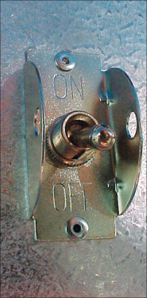
Ok, let’s move on. Where is the power supply located (see 600.21)? The particular sign we discussed earlier had access panels close to each power supply and to other electrical components. If not, how do we access this equipment? Our location is to have an access door (3 ft by 2 ft), and a walkway at least 1 ft wide from opening to equipment. We need to see what we are doing when we are working. Sections 210.70(C) and 600.21(E) tell us that equipment requiring servicing needs a lighting outlet switched at the point of entry.
Controllers can serve different functions
The controller is also covered under 600.6(A)(2) and (B) (see figure 7). This section gives the location for the controller disconnecting means (switch). Also, this switch (if not within sight of the controller) shall be capable of being locked in the open position. These controllers can serve different functions, such as servicing the neon letters and the rolling lamps under or around the sign.
Now let’s look at how we tell the controller what functions to perform. In most cases, there is a data cable running from an office with a programming unit (see figure 7). We will need to look at Article 725 to find the code requirements for this installation. First, we need to determine what Class power supply we have. In this case, we have a Class 2 as described in 725.121(A)(1) or (2). Do any other sections such as in 725.3 apply? Most of the time, we will reference the wiring methods of Article 300 based on 725.130(A) and (B), but we need to make sure the method is secured in a neat and workmanlike manner (725.24) if the cable is not in a raceway. And, lastly, with this equipment, is it listed as per 110.3?
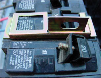
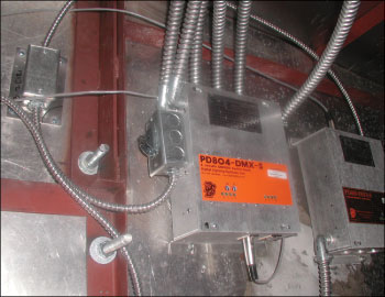
Photo 6. Lock-out device
Tubing installation methods
Fluorescent cabinet
Recessed luminaires
Now what other electrical equipment will concern us? Recessed luminaires, as outlined in Parts XI and XII of Article 410. We need to check the supporting of the luminaries and wiring methods [see 410.30(A), 410.116, 410.117 and 410.118 and for illustration, see figure 9]. The recessed cans need to be secured to the frame of the sign body by an approved method acceptable with your AHJ. Clearances (depending on the material of the sign body) must be maintained. If the sign is outdoor and exposed to high heat, the conductor insulation must be suitable for the temperatures encountered and not in excess of 90ºC (194ºF).
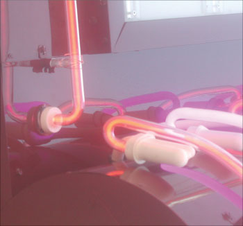
Photo 7. Weatherproof boots
In closing, we have looked at some of the aspects of inspecting a typical sign. Sign inspections do not need to be difficult, just remember the basics. NEC requirements are the minimum requirements. Listed materials and components are available. Use listed products as intended. Signs are to be on their own circuits. Switches need to be within sight of the sign body, or capable of being locked out. Grounding, regardless of the voltage, needs to be maintained. After the basics check, see if you have other factors such as data connections, controllers to operate additional functions, luminaires attached to your sign, or skeletal neon tubing on the sign. With high voltages come increased hazards and concerns. Inspectors and installers should work together to achieve code-compliance and safe installations. Communication and education are the keys. You need to understand the basics; then use references to help you with the rest, a good example would beNeon Lighting, A Professional Advantagefrom IAEI.
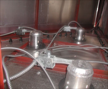
Photo 8. Inside the sign — Always verify that all wiring methods are properly terminated and secured.
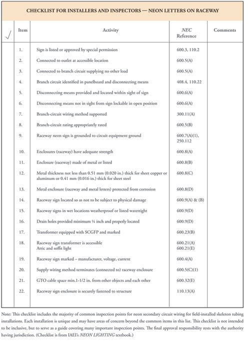
Table 1



Find Us on Socials