 NEC Article 100 defines a controller as “a device or group of devices that serves to govern, in some predetermined manner, the electric power delivered to the apparatus to which it is connected.” Section 430.2 gives a more motor-specific definition: “For the purpose of this article [Article 430], a controller is any switch or device that is normally used to start and stop a motor by making and breaking the motor circuit current.”
The magnetic motor starter is such a controller and utilizes electromagnetically operated contacts that start and stop the connected motor load. A control circuit with momentary contact devices connected to the coil of the magnetic motor starter performs this start and stop function. A three-pole full-voltage magnetic motor starter is made up of the following components: set of stationary contacts, set of movable contacts, pressure springs, operating coil, stationary electromagnet, set of magnetic shading coils, and the moving armature.
It is also important to remember that a magnetic motor starter is a contactor that has the addition of an overload relay assembly that provides running overload protection to the motor. Selection of the thermal overload relay is done using the manufacturer’s table included with the magnetic motor starter. It is always important to know the full load current (FLC) of the motor, the service factor (SF) of the motor, and the ambient temperature in which the equipment is being operated. Thermal units are based on an ambient temperature of 40° C (104° F).
Types of starters
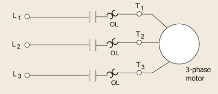
Magnetic motor starters are commonly available as full-voltage (across-the-line), reduced-voltage, and reversing. A full-voltage or across-the-line magnetic motor starter applies full voltage to the motor, which means it is designed to properly handle the levels of inrush current that will develop as the motor is started (see figure 1).

Figure 1. Full-voltage (across-the-line) magnetic motor starter
Reduced-voltage starters are designed to limit the effects of inrush current during motor startup. These are available in electro-mechanical and electronic formats.

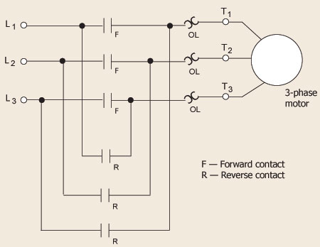
Figure 2. Full voltage reversing starter
Reversing starters are designed to reverse shaft rotation of a three-phase motor. This is accomplished by interchanging any two-line conductors that supply the motor load. The reversing magnetic motor starter features a forward and a reverse starter as part of the assembly (see figure 2). Electrical and mechanical interlocks are provided to ensure only the forward or the reverse starter can be engaged at any given time, but not at the same time.
Comparison of NEMA and IEC starters
In this article we will focus on how NEMA (National Electrical Manufacturers Association) and IEC (International Electro-Technical Commission) relate to the selection and application of magnetic motor starters.
NEMA magnetic motor starters are available in various voltage and horsepower ratings with the following designations: sizes 00 through size 9, consecutively. These NEMA sizes classify a magnetic motor starter by voltage and maximum horsepower. Examples of AC voltages include 24V, 120V, 208V, 240V, 277V, 480V and 600V varieties. The magnetic motor starter is also offered in different types of enclosure depending on the environment in which the equipment will operate, not to mention DC coils. Typical protective enclosures are NEMA 1 (general purpose), NEMA 4 (watertight), NEMA 12 (dust-tight) and NEMA 7 (hazardous location).
IEC-style magnetic motor starters are usually available in a modular format with a contactor and an overload relay. Three-phase contactors are available in 208V, 230V, 460V and 575V variety with corresponding maximum horsepower ratings. IEC magnetic motor starters are often supplied as part of original equipment manufacturer (OEM) equipment, as are NEMA starters.
If we compare the NEMA magnetic motor starter to the IEC magnetic motor starter, we would notice the following differences:
IEC device typically is physically smaller than the comparable NEMA device but not in all cases, especially in larger sizes.
The life cycle can be different between NEMA and IEC devices. Performance evaluation between NEMA and IEC, as well as variances in how manufacturers develop the data (not validated by 3rd parties so test methods could vary greatly). The general safety performance of either IEC or NEMA devices is evaluated by a 3rd party testing agency in North America. The EU does permit self-certification, but manufacturers of NEMA devices also use self-certification for NEMA-specific performance characteristics. A NEMA controller is typically from an OSHA accredited lab, while an IEC device may be self-certified, with a CE mark, or certified by a lab that may not be OSHA accredited. NEMA starters can now be used in conjunction with electronic/solid state overload relays that are adjustable.
IEC device has an adjustable overload relay assembly, while the comparable NEMA device has a fixed and removable overload relay assembly. In addition, NEMA devises can be used in conjunction with electronic/solid state overload relays that are adjustable.
IEC device should normally be protected with fast-acting current-limiting fuses, while the NEMA device can be protected with conventional time-delay fuses, but this varies from product to product and from manufacturer to manufacturer.
Many IEC and NEMA devices are designed for use with conventional (non–current-limiting) fuses and circuit breakers, at least for standard fault SCCRs. Fact-acting, current-limiting may be used for high fault SCCRs and/or Type 2 coordination.
The end user should carefully consider all these requirements before making the decision to install a NEMA magnetic motor starter or an IEC magnetic motor starter in their specific application.


Find Us on Socials