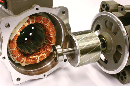
 Magnetism and its effects are keys to understanding the operation of a motor. Lodestone, a natural mineral, exhibits the characteristics of a bar magnet that has a north pole and a south pole — always. I say always because if you were to cut a bar magnet in half, the magnetic domains of the two new pieces would re-orient themselves to corresponding north and south poles. I am sure everyone remembers the law of magnetic attraction: like magnetic poles repel each other; unlike magnetic poles attract each other. It is also important to realize that the earth generates its own magnet field and, in effect, operates like a gigantic bar magnet, having a north and a south pole.
Connection between Magnetism and Electricity
The first observer of the connection between magnetism and electricity was the Danish physicist Hans Christian Oersted. He accidentally discovered this relationship when, during a public lecture, he noticed how a compass needle moved when placed near a current-carrying conductor. This simple experiment illustrated how a current-carrying conductor produces amagnetic field. This was the first recorded account of the interaction between the magnetic field and the electric field.
But, if an electric current can produce a magnetic field, can a magnetic field produce an electric current? English physicist Michael Faraday discovered this principle which is known asmagnetic induction. If a bar magnet is moved within a coil of wire, an electric current is generated. This law is also helpful in understanding how transformers work with a primary and secondary coil. The Right Hand Rule gives us a graphical way to examine the interaction between magnetism and electricity. The idea is to grasp a current-carrying conductor with your right hand and place your thumb in the direction of current flow. Your remaining fingers curl in the direction of the magnetic field around the conductor.
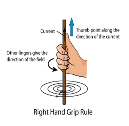
Figure 1. This rule illustrates the interaction between magnetism and electricity.
By definition an electric motoris a device that converts electrical energy into mechanical energy. An electrical signal is applied to the input of the motor and the output of the motor produces a defined amount of torque related to the characteristics of the motor. If you think about the attraction and repulsion of the north and south poles of a bar magnet, you are on your way to understanding what has to happen inside the motor yoke. To achieve rotation there has to be some interaction between magnetic flux produced by electromagnetism within the motor. DC motors and AC motors accomplish this task in different ways.
DC Motors
DC machines can be classified as self-excited, separately excited, permanent magnet (PM) or brushless. Self-excited machines can be further classified as shunt, series, and compound. Compound machines can be further classified as cumulative and differential. Cumulative and differential machines can be further classified as long shunt and short shunt. As you can see there are a variety of electrical configurations for a DC machine. For the purposes of this article, we will stay with the series and shunt-wound DC motor. Please note that the interconnection of the field (stationary winding) and armature (rotating winding) determine the machine’s operating characteristics.
The shunt DC motor has the field winding in parallel with the armature. In a parallel circuit themagnitude of voltage dropacross each parallel element is the same, while themagnitude of currentthrough each parallel branch is a function of the impedance of the element. Please note, in a purely resistive circuit the impedance will equal the resistance as there is no reactive component present. Shunt motors are also called constant-speed motors as they provide relatively stable speed and torque characteristics under load.
The series DC motor has the field winding in series with the armature. In a series circuit, themagnitude of currentis the same through all series elements, while themagnitude of voltage dropacross each series element is as function of the impedance of the element. Series motors can develop very high starting torque and provide excellent torque characteristics under load. The drawback is speed regulation; so a series motor is never recommended to be operated without mechanical load present.
DC Terminology
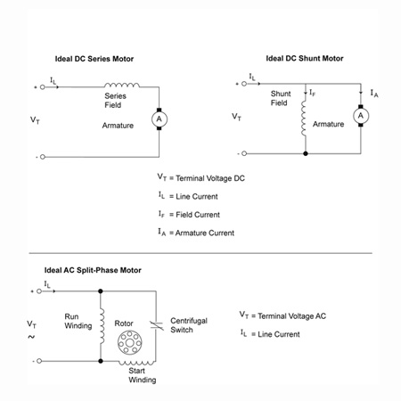
Figure 2. Circuit diagrams for a series and shunt DC motor and for an AC split-phase motor.
Common terms you will hear discussed with DC motors are: commutators, brushes, counter electromotive force (EMF), torque, speed regulation and speed-torque characteristic curves. Thecommutatoris a mechanical device and when used in a motor application properly, it directs current flow to the armature. By contrast, when a commutator is used in a generator application, it acts like a rectifier to convert the generated AC voltage of the machine into DC voltage.Brushes, which are usually made of carbon, are used to transition from a stationary element to a rotating element.Electromotive forceis “the difference in potential that exists between two dissimilar electrodes immersed in the same electrolyte or otherwise connected by ionic conductors.” The terms EMF and voltage are often used interchangeable. Remember Faraday’s law of magnetic induction where a magnetic field can generate an electric current? As it turns out in the case of a DC motor, when the armature rotates through the magnetic field, an induced voltage opposite in polarity to the applied voltage is created and this is calledcounterEMF.
Torqueis a rotational force that, in its simplest terms, is the algebraic product of force multiplied by distance. Anyone who has worked on switchgear or feeder busway is familiar with a torque wrench.Speed regulationis a measure of how the speed of a DC motor decreases as more mechanical load is applied. It is a function of the armature resistance.Speed-torque characteristic curvesare graphs that show the relationship between speed as a percent of rated speed vs. load torque as a percent of full rating. These terms are very helpful as they will illustrate how applied mechanical load will affect the speed and torque of series, shunt, or compound DC machines.
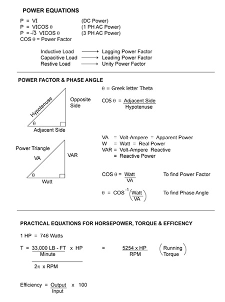
Table 1. Power equations for DC, single-phase AC and three-phase AC. It also includes a graphical aid called the power triangle, which utilizes trigonometric identities to help with the analysis of power factor. Finally, some practical equations are included to calculate horsepower, torque, and efficiency.
AC Motors
AC machines can be classified as induction, wound rotor, and synchronous. Induction motors can be further classified as three-phase and single-phase. Three-phase induction motors can be further classified as delta-wound or wye-wound. Single-phase motors can be further classified as split-phase, capacitor-start, capacitor-start/capacitor-run, shaded-pole, repulsion start, and universal. Again, as you can see, there are several varieties of AC motors, and I have tried to list the more popular industry types. Again, for the purposes of this article, we will stay with an overview of the induction motor.
The induction motor is commonly referred to as a “squirrel cage” induction motor. This is due to the fact that the rotor is constructed in a manner resembling a squirrel’s cage. An induction motor has a rotor (rotating part) and a stator (stationary part) within the motor housing. When an AC signal is applied to the stator winding, a rotating magnetic field is produced. This rotating magnet field, in turn, induces a signal in the rotor, which also generates a rotating magnetic field. The interaction of these rotating magnetic fields causes rotation. This is an important principle to keep in mind; because, in the case of a DC motor, the magnetic field is not time varying due to the applied signal.
AC Terminology
Common terms you will hear discussed with AC motors are: frequency, synchronous speed, and slip. An AC waveform is time varying or oscillatory. This means its amplitude starts at zero, rises to some maximum value, returns to zero, falls to some minimum value, and then returns to zero. The number of times this occurs per unit of time is referred to asfrequency. In the United States, our frequency is 60 Hertz or 60 cycles per second.Synchronous speedrefers to the speed of the rotating magnetic field, and it is a function of the applied frequency and the number of stator poles in the machine.Slipis a measure of the difference between the synchronous speed of the stator field rotation, and the rotor field rotation. Please note that the rotor field rotation is always slower than the stator field rotation.



Find Us on Socials