When buying real estate, conventional wisdom dictates the three most important elements are—Location, Location, and Location.
Based on my twenty-six years of working with PV systems, including the school of hard knocks, I strongly feel that the three most important elements to long- and short-term PV safety are—Grounding, Grounding, and Grounding.
Utility-interactive residential (dwelling unit), commercial, and megawatt PV systems operate with dc voltages from 50 volts to 600 volts and higher. AC voltages start at 120 and go to 23 kV on some of the larger systems. Underwriters Laboratories (UL) has determined that there is a shock hazard in exposed circuits operating at over 30 volts (ac or dc) in wet locations. SeeNEC690.31(A) and 690.33(C).
Operating currents range from less than 10 amps dc and ac to about 2200 amps dc on some of the larger inverters. An arc at currents around 1 amp can start a fire in the right material. Module power can be as low as 20 watts, but ranges upward to 320 watts. Consider the small 7-watt night-light or Christmas tree bulb (before LEDs). Seven watts can start a fire.
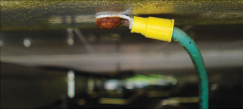
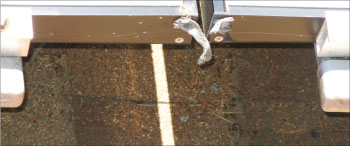
Photo 1. Improper module grounding: Plated steel thread cutting screw is not corrosion resistant; THHN conductors and nylon lug are not UV-rated.
PV modules and wiring as well as outdoor-mounted inverters are subjected to severe environmental conditions. Rain, sleet, snow, hail, sand, wind, and sunlight coupled with low and high temperatures would wear down the most stalwart postal worker over a 40–50 year span—the life expectancy of a PV module for producing dangerous amounts of voltage and current. USE-2 cables and the new PV cables are some of the toughest generally available cables, and we have seen USE-2 holding up well after 25 years when properly installed; but what about a less-than-outstanding installation after 30 or 40 years?
The environmental conditions, the use of copper conductors to ground aluminum module frames, and the daily thermal cycling that terminals, combiners, and modules are subjected to will eventually cause a break down in the insulations involved or in the electrical connections.
Proper grounding is a must, even when the NEC and the UL Standards do not fully addressthe issue.
Grounding Problems Are Being Observed and Reported
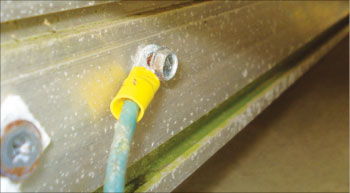
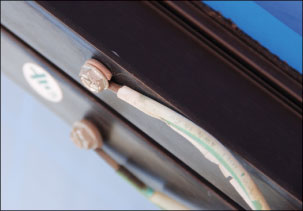
Unfortunately, getting the PV modules and racks grounded in a manner that will yield a low-resistance connection to the grounding system that will last for 50 or more years appears to be difficult. Inspectors are seeing improper grounding techniques being used (see photos 1, 2 and 3.) Improper grounding instructions are even appearing in the instruction manuals for listed PV modules (see photo 4). Inspections and tests of installed PV systems have found that in some cases, module-grounding connections have deteriorated in as little as three years and sooner in some areas (see photos 5 and 6).
There is significant confusion among module manufacturers, PV installers, and inspectors concerning how to properly ground a PV module; that confusion is becoming more and more apparent as numerous PV systems are being installed. A little history may highlight the cause of this confusion.
A Look at UL Standard 1703
Bonding the frame pieces together in the factory using very specific materials and methods results in a durable electrical connection between the frame pieces so that any failure in the module insulation or external conductor insulation will result in all pieces of the frame receiving equal voltage. The factory bonding also insures that when the module frame is properly field-grounded at one of the marked and tested points, the entire module frame is maintained at the ground potential under fault conditions.
During the bonding process, all screw fasteners are precisely torqued to the specified value by automated equipment or by trained technicians using torque screwdrivers. The factory bonding materials and methods are evaluated for low resistance and durability during the listing process. Subsequent to the listing, if the manufacturer changes any of the bonding materials or methods, the changes must be reevaluated by the listing agency. The materials (including any screws or washers) are not specified generically; they are specified to the original equipment manufacturers (OEM) and must always be obtained and used from those sources unless any change is reevaluated by the listing agency.
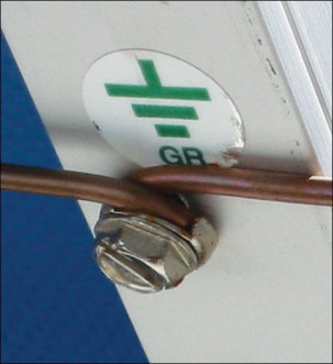
Photo 4. Installed per instruction manual—but copper touching aluminum?
Contrast this precisely controlled and evaluated factory bonding system with the field-installed grounding techniques used to connect a copper equipment-grounding conductor to the aluminum module frame. Grounding PV modules is haphazard at best for a number of reasons. The first is that the module manufacturers do not realize the importance of this connection to the overall safety of the system. Second and possibly the most critical is that the Bonding/Grounding section in UL 1703 does not clearly distinguish the differences between bonding and grounding. The manufacturers have the impression that the bonding techniques and materials used in the factory may be applied to the grounding connections made by the installer in the field. Instruction manuals and hardware (sometimes supplied) show techniques which are not consistent with good electrical connections (see photo 4). Field-made connections using a threaded fastener are rarely torqued to the specified value, even when that value is given in the module instruction manual, because few PV installers have or carry torque screwdrivers. The field grounding connection may or may not be inspected by the AHJ, and they are never tested for overall continuity. Also, since the PV system can operate without trouble for many years, there is little motivation to inspect these connections after the original installation.
In late 2007, UL issued an “Interpretation” of UL 1703 which focused on module field grounding. This interpretation was to be used by module manufacturers and the module testing/certification/listing laboratories (UL, CAS, TUV and ETL) to evaluate and possibly revise the grounding methods, hardware (if any) and instructions supplied with the modules. Unfortunately, it is not possible for the laboratories to review all existing modules and supposedly modules are reevaluated every five years when the listing must be renewed. A few module manufacturers have revised their grounding instructions, but it would appear that these revised instructions in some cases may have not been carefully evaluated or even reviewed by the certification/listing laboratories.
Grounding Instructions Not Consistent
The UL Interpretation of UL 1703 has very specific information about not putting dissimilar metals into contact and gives a chart that shows the compatibility of various metals. Copper and aluminum may not come in contact and if they do, the aluminum at the contact point will be removed by galvanic corrosion destroying the connection. Inadvertent contact between the bare copper equipment-grounding conductor and an aluminum module frame or rack does not pose problems because the small amount of aluminum that may disappear is not involved in a specific electrical contact.
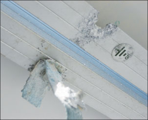
Photo 6. Tinned copper braid offers no protection for aluminum module frame.
In some cases, the instructions specify the use of a stainless-steel washer to isolate the copper conductor from the aluminum frame, but no surface preparation of the oxidized, anodized, and/or clear-coated aluminum module frame is specified. If this method were to be done properly with surface preparation, then the presumption is that the mechanical fastener (screw and nut) and the stainless steel washer would carry the fault currents. But these devices are generic in nature and have not been evaluated for carrying current.
A casual examination of any common electrical device such as a circuit breaker, a receptacle outlet, or a wall switch will show that the mechanical fastener provides only pressure to push the two electrical conductors together. Those mechanical fasteners (screws) are not normally designed or specified to carry currents, unless they have been specifically tested and evaluated to do so during the listing of the device. An example of a device where the provided screw has been evaluated to carry current is the neutral-to-ground bonding screw used in many service-entrance panels.
To further confuse the situation, it appears that the high currents, steel plates, and test methods used in UL Standard 467 for evaluating and listing grounding devices may not be applicable to evaluating grounding devices used to ground PV modules and racks where the currents are low and the aluminum surfaces are oxidized, anodized or clear coated.
Help Is Coming
AHJ comments on poor grounding and confusing grounding instructions to the UL AHJ reporting web site may speed the process, as UL is made more aware of the pressing problem.
http://www.ul.com/global/eng/pages/offerings/perspectives/regulator/electrical/productreport/
Although not presently on the market, some modules have been built with plastic frames—maybe they will return.
When the grounding instructions furnished by the module manufacturer are inadequate or contradict NEC or UL requirements, the PV installer and the inspector must come to some agreement on what is an acceptable module grounding method and hardware.
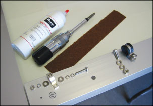
One method used by utility companies for many years to connect copper conductors to aluminum busbars in an outdoor environment uses surface preparation and a tin-plated copper lay-in lug listed for direct burial. A description of this method was presented in The “Perspectives on PV” column in the IAEI News for September-October 2008. It may also be found in the Burndy instructions for installing lay-in lugs and in Appendix G of the NEC/PV Suggested Practices manual. Both may be found on my web site—below. (See photo 7).
Summary
Grounding is critical to the short- and long-term public safety of PV systems. These systems may be producing power 50 years from the installation date with possibly deteriorating electrical connections and insulations. Grounding all exposed metal surfaces for the life of the systems is mandatory, and the techniques used may have to exceed existing Code and UL requirements.
What are you waiting for?
For Additional Information
If this article has raised questions, do not hesitate to contact the author by phone or e-mail. E-mail: jwiles@nmsu.edu Phone: 575-646-6105
A color copy of the latest version (1.9) of the 150-page,Photovoltaic Power Systems and the 2005 National Electrical Code: Suggested Practices, written by the author, may be downloaded from this web site: http://www.nmsu.edu/~tdi/Photovoltaics/Codes-Stds/Codes-Stds.html
The Southwest Technology Development Institute web site maintains a PV Systems Inspector/Installer Checklist and all copies of the previous “Perspectives on PV” articles for easy downloading. Copies of “Code Corner” written by the author and published inHome Power Magazineover the last 10 years are also available on this web site: http://www.nmsu.edu/~tdi/Photovoltaics/Codes-Stds/Codes-Stds.html
For an intensive 7–8 hour training session on PV and the NEC, see the web site above for a schedule of presentations made to inspectors, electricians, electrical contractors, and PV professionals. The hosting organization usually charges a very nominal fee and controls registration and attendance


Find Us on Socials