Question
When using a 90°C single conductor in an ambient temperature of 81°C – 89°C, what is the correction factor for this application? It is presumed once the temperature reaches 90°C the conductor has met or exceeded its rating. Is there ampacity present in this conductor at 85°C, however minimal it may be?
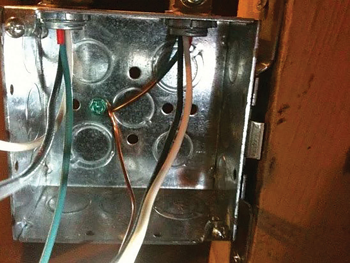
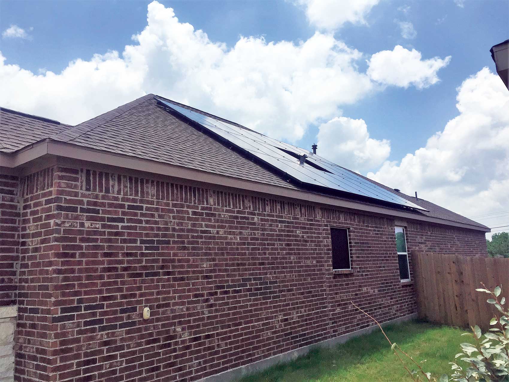
There is no clarification or note in theNECto address this issue. Since the table stops at 80°C, the 9-degree temperature omission is left up to inspectors and contractors to interpret and to argue this issue in the field. This issue has arisen due to photovoltaic module installation. The modules are sold with factory installed 90°C USE-2 or RHHW-2 single insulated conductors. These modules are sometimes installed close to roof surfaces with little airflow (building integrated photovoltaics), trapping heat under the module where the conductors are located. Therefore, the conductor may be exposed to ambient temperatures in excess of 80°C. Article 690 doesn’t address this issue either. Table 310.16 has the same issue, although it is for cables or conductors installed in raceways. — J. E.
Answer
You are correct, there are no correction factors in 81–90 degree column; this is a good place for a code change.
Let’s take a closer look at theNEC. The issue here is 310.10 that states, “No conductor shall be used in such a manner that its operating temperature exceeds that designed for the type of insulated conductor involved. In no case shall conductors be associated together in such, with respect to the type of circuit, the wiring method employed, or the number of conductors, that the limiting temperature of any conductors, that the limiting temperature of any conductor is exceeded.”
The problem here is that some people want to use the highest temperature the conductor will ever see for the correction factor when you only need to use the average high-ambient temperature depending on what climate you are in. Some average outdoor ambient temperatures for selected cities during the period of June to August are shown below. These temperatures are based on ASHRAEHandbook of Fundamentals2 percent design temperatures and are measured in the shade, not in the sun.
City Average high ambient
Phoenix, AZ 109.5°F
Bakersfield, CA 102.7°F
Los Angeles, CA 78.6° F
Long Beach, CA 86.9°F
Palm Springs, CA 110.9°F
I realize that the solar equipment is in the sun, hopefully. This may add to the actual temperature as it did for raceways on roofs exposed to direct rays of the sun. NEC-2008 had a proposal with two code cycles of testing substantiations that was accepted to have a correction adder for raceways in direct rays of the sun on a roof [310.15(B)(2)(c)]. Panel 6 has seen no testing, or request for conductors, or for solar equipment, or ampacity correction in direct rays of the sun for solar to have an adder to the correction factors. Panel 6 will need true documented testing photos, etc., before the panel will act.
At this time, we electrical inspectors can only require the average high temperature for our calculations.
For example, Palm Springs has an average high temperature of 110.9°F. You stated that you are using single conductors. That allows you to use Table 310.17 for the allowable ampacities. Using a 90 degree, 10 AWG rated at 55 amps x .87 at 110 degrees = 47 allowable amps.
The higher temperatures are not prolonged, they may be for a few hours a day and probably periodic through the year. Section 310.10 FPN No.1 explains. “The temperature rating of a conductor [see Table 310.13 and Table 310.61] is the maximum temperature, at any location along its length, that the conductor can withstand over a prolonged time period without serious degradation. The allowable ampacity tables, the ampacity tables of Article 310 and the ampacity tables of Annex B, the correction factors at the bottom of these tables, and the notes to the tables provide guidance for coordinating conductor sizes, types, allowable ampacities, ampacities, ambient temperatures, and number of associated conductors.”
2008 Change for raceways on roofs
Some examples of the affect on conductor ampacity when temperature adders for conductors in raceways in direct sunlight on rooftops are applied are shown below.
Example 1:
12 AWG THHW-2 in 1/2 in. RNC or EMT installed with the bottom of the RNC or EMT 1/2 in. or less above the rooftop (most severe condition)
Table 310.16 90°C ampacity = 30 amps @ ambient temperature of 30°C.
Temperature adder from Table 310.l5(8)(2)(c) for raceway location = 33°C.
Adjusted ambient temperature = 63°C (30°C + 33°C).
Table 310.16 correction factor for 63°C ambient, 90°C conductor = 0.58.
Adjusted ampacity (30 amps x 0.58) = 17 amps.
240.2 overcurrent protection limitation = 20 amps.
Since the adjusted ampacity is 17 amps, the standard fuse or circuit breaker rating would be 20 amps [see 240.2(8)].
Example 2:
3/C 500 kcmil THHW-2 in 2 1/2 in. RNC or EMT (NEC Table C.I) installed with the bottom of the RNC or EMT 3 1/2 in. to 12 in. above the rooftop.
Table 310.16 90°C ampacity = 430 amps @ ambient temperature of 30°C.
Temperature adder from Table 310.15(8)(2)(c) for raceway location = 17°C.
Adjusted ambient temperature = 47°C (30°C + l7°C).
Table 310.16 correction factor for 47°C ambient, 90°C conductor = 0.82.
Adjusted ampacity (430 amps x 0.82) = 353 amps.
Comparison: Table 310.16 75°C ampacity = 380 amps @ ambient temperature of 30°C
As you see, the further from the roof, the more circulation is available. However, this Code change was for raceways and there were no proposals for solar conductors, unless they are in a raceway on the roof. — John Stacey, CMP-6


Find Us on Socials