Photovoltaic (PV) systems will be producing hazardous voltages and currents for 50 years or more. Over that period of time, they may or may not be operational and they may or may not be maintained. Proper grounding of all exposed metal surfaces in the system that may be energized by internal faults, poor terminations or failing conductor insulation is one of the most important requirements in a code-compliant system. Even in a failing or failed system, maintaining all metal surfaces at ground (or earth) potential will minimize the possibility of electrical shocks. Those grounding connections must be maintained in a harsh outdoor environment where they are exposed to heat and cold, solar radiation (ultraviolet radiation and added heat), dirt, rain, wind, ice, sleet, and snow.
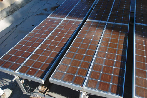
Photo 1. Aged PV modules – still producing power
Why is grounding PV different from grounding HVAC?
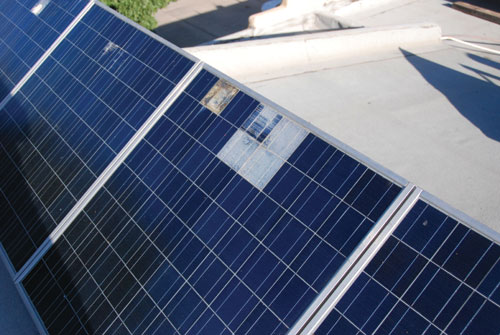
PV modules, with an active life measured in many decades, will be in place longer than the outdoor unit of a HVAC system. When the performance of an HVAC system deteriorates, it is usually inspected and repaired promptly. PV systems suffer gradual degradation that is not usually monitored, and the PV array may remain installed on the roof even after the system has been decommissioned or abandoned when the inverter fails—a common occurrence when sufficient funds are unavailable to make the inverter repair or replacement. (See photos 1 and 2).
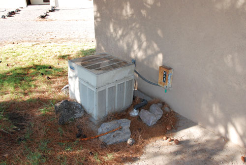
Photo 3. HVAC outside unit, well maintained and with single grounding point
HVAC units have only a few separate pieces, the equipment grounding points are well marked, and the factory installed bonding jumpers and screws effectively bond all parts of the listed device together (photo 3). HVAC components are typically made of steel and the equipment-grounding terminals are electrically and chemically compatible with copper conductors.
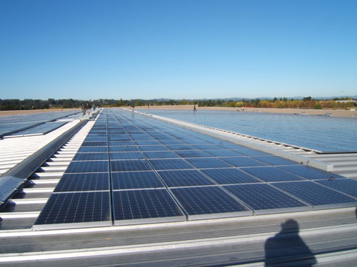
Photo 4. Thousands of PV modules in a large array, each to be grounded
On the other hand, PV systems have numerous modules (tens to thousands) and mounting racks that must be individually grounded (photo 4). PV modules and mounting racks are typically made of aluminum and are not compatible with copper conductors. See “Perspectives on PV” in the September-October 2004 and March-April 2008IAEI Newsfor issues related to grounding aluminum-framed PV modules.
Are we getting better?
Inspectors throughout the country have been flooding Underwriters Laboratories (UL) with e-mails about poor PV module and PV system grounding techniques and equipment that they are seeing in the field (photo 5). And, as a result, UL is getting tough on grounding. In the fall of 2007, UL issued an “Interpretation” of the existing standard for PV modules (UL 1703). The current state of affairs with respect to grounding is in part due to a confusing section in UL 1703 that combines bonding requirements and instructions
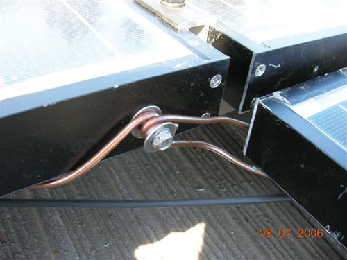
Photo 5. Poor PV module grounding
(connecting the module frame parts together in the factory) with grounding requirements (installing the external equipment-grounding connection in the field) in one section. Methods and equipment used in the factory to bond the module frame sections together are evaluated during the listing process. However, the same level of scrutiny cannot be applied to field-installed, equipment-grounding methods, and the same parts and techniques used in the factory are generally not appropriate in the field.
The Interpretation clarifies the intent of the standard in several areas:
1. Dissimilar metals, like copper and aluminum, cannot come into contact with one another at the equipment-grounding connection point. A chart is provided showing numerous metals and which types can be in contact without galvanic corrosion problems.
2. Any threaded fastener used for grounding must pass the same durability tests as any threaded fastener used for other electrical connections. It must be fastened and unfastened ten times without damage to the threads. This requirement will probably result in the demise of the use of thread-cutting or thread-forming screws for module grounding because threads in soft aluminum cannot pass this requirement.
3. The module manufacturer must provide or designate the specific hardware and methods used to ground the module, and those instructions must be included in the module instruction manual. UL will evaluate the grounding hardware and methods throughout the entire testing and listing/certification process on new modules and also when existing modules come up for recertification.
UL is also working on changes to UL 1703 that will clarify the requirements, markings, and instructions for grounding PV modules. At some point, they will develop a separate standard that will allow the evaluation and listing of various universal PV module grounding methods and devices that will work with a number of different module frame geometries. The use of this standard will allow grounding-device manufacturers to meet the standard without having to be tested with each and every separate type of PV module.
In the meantime…
As theCoderequires, instructions and labels provided with a certified/listed product must be followed [110.3(B)]. The listing and certification process is slow, and modules only come up for review every five years. Therefore, it may be some time before all of the instruction manuals meet the clarified intent of UL 1703. And this brings us to the question of new grounding devices
New grounding devices
With respect to new PV module grounding methods and devices, such as clips and washers, the situation is somewhat murky. Of course, the local AHJ can call it as they see it and some jurisdictions have accepted these new devices.
As mentioned above,NEC110.3(B) requires that the instructions and labels provided with a listed product be followed. PV modules are marked for grounding at specific points. Hardware (when provided) and these instructions require the use of the marked points. The instructions do not generally address grounding the module at the mounting holes or at other locations.
A few manufacturers may have tech bulletins that show other methods. These tech bulletins may or may not have been reviewed by UL where they differ from the listed grounding points. UL is attempting to review new manuals and directions submitted by the manufacturer, but at times, the manuals get published without a proper review. Also, even if reviewed, they may not be in compliance with allNECrequirements or may show grounding techniques that have not withstood the test of time. The future UL Standard for PV Module Grounding Methods/Devices will evaluate the long-term durability and reliability of the various grounding methods and devices.
When using a new grounding method, other than a separate wire to each PV module, grounding continuity must be addressed. One of the oldest requirements in the Code is to make a grounding connection first and break it last [250.124(A)]. Consider a module with an internal ground fault to the frame. If the circuit conductors are left connected and the module is unbolted from the grounded rack (disconnecting the frame grounding first rather than last), the module frame may be energized with up to 600 volts to the grounded rack.
Photo 6. One module grounding method
A few PV module manufacturers have listed their grounding devices and racks with specific PV modules so they have a listed combination. Rack manufacturers also are developing grounding devices, but they are not associated or listed at the present time with any particular module.
See Appendix G in the latest version (1.8) of the PV/NEC Suggested Practices Manual for the grounding method we currently use at SWTDI (photo 6). This method is used only if it does not conflict with the module instructions and when those instructions allow the use of a properly listed lug attached to the marked grounding points after appropriate surface preparation has been accomplished.
I have long been encouraging module manufacturers to get their modules tested with these new grounding products and get that information into the instruction manuals, so the AHJs won’t have any questions and the installation will be code-compliant.
TheNECis not holding up any new grounding device or method and Section 690.43 ofNEC-2008 allows the use of these new devices as soon as they have been listed/certified and identified for the use and appear in the module instruction manuals.
We aren’t connected to Mother Earth yet
A related question that will eventually have to be addressed is: To what are these new grounding devices attached? It is necessary to first verify that they can make a durable connection with the module frame, and then the device must make a connection to an acceptable grounding electrode (such as building steel) or to an accepted equipment grounding conductor such as a copper conductor? Aluminum module mounting racks are not currently listed as equipment grounding conductors, but some of the rack manufacturers are getting such a certification/listing. This is necessary because the racks are typically designed for mechanical durability and not electrical connections. Joints may be designed to allow for thermal expansion and contraction, and with aluminum, such “slop” does not make for good electrical conductivity. As theCoderequires for loosely jointed metal raceways (250.98), a provision for electrically bonding the sections of the rack together must be incorporated into the design.
Where we want to be
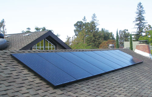
Photo 7. Integrated modules, rack, conductors, and grounding connections
For Additional Information
If this article has raised questions, do not hesitate to contact the author by phone or e-mail. E-mail: jwiles@nmsu.edu Phone: 575-646-6105
A color copy of the latest version (1.8) of the 150-page, Photovoltaic Power Systems and the 2005 National Electrical Code: Suggested Practices, published by Sandia National Laboratories and written by the author, may be downloaded from this web site: http://www.nmsu.edu/~tdi/Photovoltaics/Codes-Stds/Codes-Stds.html
The Southwest Technology Development Institute web site maintains a PV Systems Inspector/Installer Checklist and all copies of the previous “Perspectives on PV” articles for easy downloading. Copies of “Code Corner” written by the author and published inHome Power Magazineover the last 10 years are also available on this web site: http://www.nmsu.edu/~tdi/Photovoltaics/Codes-Stds/Codes-Stds.html
The author makes 6–8 hour presentations on “PV Systems and the NEC” to groups of 40 or more inspectors, electricians, electrical contractors, and PV professionals for a very nominal cost on an as-requested basis. A schedule of future presentations can be found on the IEE/SWTDI web site.